Volkswagen Golf Service & Repair Manual: Assembly overview - selector mechanism, manufacturer ZF
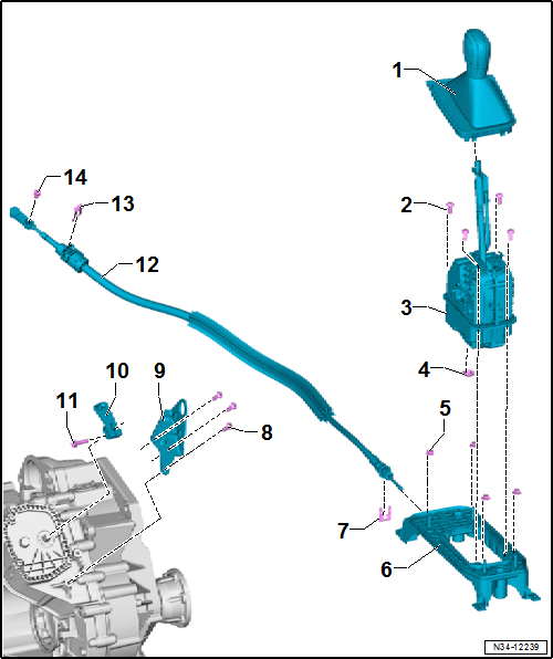
| 1 - |
Handle with selector cover |
| Do not remove handle without reason. Emergency release from position
P
→ Chapter |
| Removing and installing
→ Chapter |
| Moving push button to installation position
→ Chapter |
| With integrated selector lever sensor control unit -J587- with
selector lever -E313-, Tiptronic switch -F189-, switch for selector
lever locked in P -F319- and selector lever lock solenoid -N110- |
| Removing and installing
→ Chapter. |
| 9 - |
Cable support bracket |
| 10 - |
Gearbox selector lever |
| 12 - |
Selector lever cable |
| Removing and installing
→ Chapter |
| Checking and adjusting
→ Chapter |
| Adjuster screw for selector lever cable |
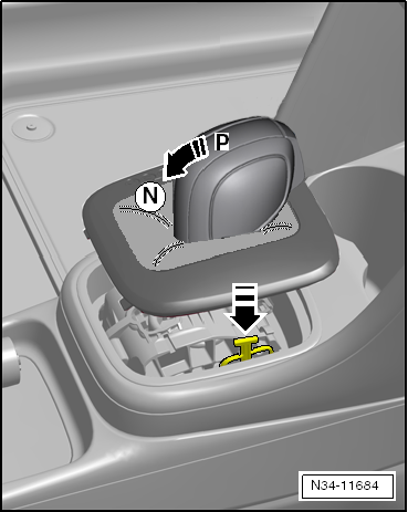
Emergency release from position P, Golf 2013 ►, Golf Estate 2014
| – |
Depress brake pedal or set handbrake. |
| – |
Open lid of storage compartment. |
|
|
|
| – |
Grasp under the cover with one hand and unclip selector
cover by pulling it upwards. |
|
|
|
| – |
Push selector cover to one side, press onto the yellow
plastic component and hold it in this position. |
| Selector lever can now be moved from position
»P«. |
|
|
|
Removing and installing selector lever handle, Golf 2013 ►, Golf Estate
2014 ►, Passat 2015 ►, Passat Estate 2015 ►
| Special tools and workshop equipment
required |
|
|
|
| Hose clip pliers -V.A.G 1275 A- |
| Handle is removed together with selector cover. |
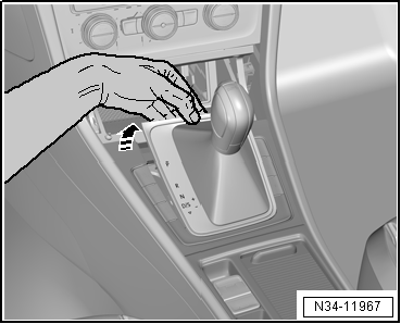
| – |
Shift selector lever to position “D”. |
|
|

|
| The push button -arrow- does
not need to be pulled out by hand. Push button engages
automatically in installation position when handle is pulled
off. |
| – |
Open lid of storage compartment. |
|
|
|
| – |
Grasp below cover with one hand and pull it upwards to
unclip it. |
| – |
Disconnect electrical connectors. |
|
|
|
| It is possible for the push button in the handle to be
pressed. Never install a handle with the push button pressed in. |
| Move push button to installation position
→ Chapter. |
|
|

|
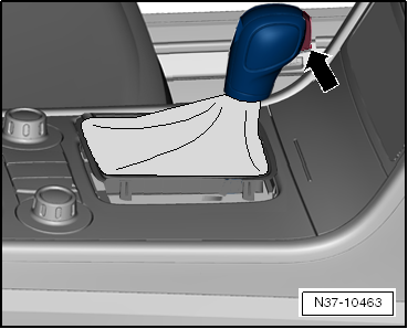
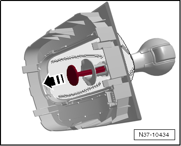
| New handle is supplied with installation guard. Do not
remove guard until just before installing. To remove, pull out
in direction of -arrow-. |
| – |
Push handle fully onto selector lever and lock. |
| – |
Push sleeve downwards to lock. |
|
|
|
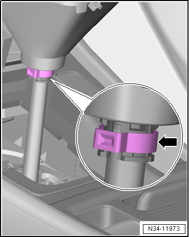
| – |
Push on handle with new clamp -arrow-
onto stop. |
| – |
Secure clip with hose clip pliers -V.A.G 1275 A-. |
| – |
Connect electrical connector. |
| – |
Push the push button after installing it. |
 Note Note
| If not installed correctly, push button remains inserted in
handle after being pressed. If this happens, remove handle again
and move push button to installation position again
→ Chapter. Then, fit the handle again. |
| – |
Clip cover in position. |
|
|
|
Assembly overview - selector mechanism ...
Special tools and workshop equipment
required
Release tool -T10534-
If the push- ...
Other materials:
Removing and installing sealing flange on gearbox side
Special tools and workshop equipment
required
Flared ring spanner tool insert AF 24 -V.A.G 1332/11-
Depth gauge -VAS 6082-
...
Petrol
First read and observe the introductory information
and safety warnings Petrol types
Fuels with a maximum ethanol content of 10% (E10) can be used for refuelling.
Petrol types are categorised according to their octane number, e.g. 91, 95, 98
or 99 RON (RON = Research Octane Number). The ve ...
Removing and installing D-pillar trim
Note
Removal and installation are described for the left vehicle
side. Follow same instructions for the right side as
appropriate.
Special tools and workshop equipment
required
...
© 2016-2026 Copyright www.vwgolf.org

 Selector mechanism
 Moving push button to installation position in the handle