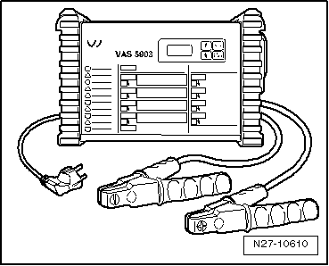
Volkswagen Golf Service & Repair Manual: Charging totally discharged battery with battery charger -VAS 5903-
 WARNING
| Danger of injury! Observe warning notices and safety
regulations
→ Chapter! |
|
WARNING
| It is not permissible to test or charge batteries
whose magic eye shows light yellow. Do not slave/jump
start the vehicle! |
| Danger of explosion when checking and charging or
slave/jump starting. |
| These batteries must be renewed. |
|
 Caution
| The terminal polarity protection in operating mode
“charging totally discharged batteries/support mode” is
not active. Connect battery charger terminal clamps
correctly to battery terminals. |
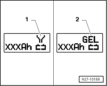
| When charging always set the battery charger to the
correct type of battery
→ operating instructions for battery chargerVAS 5903! |
| Totally discharged battery is not recognised by
battery charger
→ Chapter. |
| Do not press START / STOP
button when charger unit cables are connected
incorrectly. The charger unit may be damaged. |
|
| Batteries with a voltage of less than 2 volts will not be
recognised automatically by battery charger -VAS 5903-. |
| Special tools and workshop equipment
required |
|
|
|
| Battery charger -VAS 5903- |
 Note Note
| Observe notes in chapter
→ Chapter. |
| Totally discharged batteries in vehicles before registration
must be exchanged prior to delivery. Preliminary damage cannot
be excluded. |
| The battery must have a temperature of at least 10°C. |
| – |
Switch off ignition and all electrical consumers. |
| – |
Connect charger plug to battery charger. The last selected
operating mode will appear on display
→ Chapter. |
|
|
|
WARNING
Danger of injury! Observe warning notices and safety
regulations
→ Chapter!
...
General notes:
The support mode provides the onboard supply with power when
the battery is removed or disconnected.
For furthe ...
Other materials:
Removing and installing head restraint guide
Removing
–
Remove backrest cover and backrest padding
→ Chapter.
Right head restraint guide
–
Press locking lugs inwards -arr ...
Renewal of aerial wiring
A new approach to repair work on aerial wires has been
developed
→ Chapter.
Now connecting wires in different lengths and various
adapter cables are available as replacement parts instead of a
complete aerial wire.
...
Battery with »enhanced« colour indicator
This is a maintenance-free battery with liquid electrolyte
(wet battery).
Caution
No stickers may be removed and do not replenish with
distilled water. Only perform a visual check. Refer to
...
© 2016-2026 Copyright www.vwgolf.org

 Charging battery in refresh charge mode with battery charger -VAS 5903-
 Charging battery in support mode with battery charger -VAS 5903-