Volkswagen Golf Service & Repair Manual: Charging battery in service mode with battery charger -VAS 5900-
 WARNING
| Danger of injury! Observe warning notices and safety
regulations
→ Chapter! |
|
 Caution
| The operating mode “service charge” is not permitted
on VW vehicles as the voltage peaks will damage the
onboard electronics. |
| If there is a requirement to use “service charge”
the battery must be disconnected from the onboard
supply. |
|
WARNING
| It is not permissible to test or charge batteries
whose magic eye shows light yellow. Do not slave/jump
start the vehicle! |
| Danger of explosion when checking and charging or
slave/jump starting. |
| These batteries must be renewed. |
|
Caution
| When charging always set the battery charger to the
correct type of battery
→ operating instructions for battery chargerVAS 5900! |
| The “service mode” is suitable for: |
| Wet batteries where the magic eye allows charging
(magic eye black or green) |
|
| The operating mode “service charge (SERV)” is only used on
sulphated batteries. The battery is charged at a voltage of
> 14.4 V. This can result in a partial reduction of the
sulphated layer. After charging, always check the colour of the
magic eye before using the battery
→ Chapter. |
| Special tools and workshop equipment
required |
|
|
|
| Battery charger -VAS 5900- |
 Note Note
| The battery must have a temperature of at least 10°C. |
| – |
Switch off ignition and all electrical consumers. |
| – |
Connect charger plug to battery charger. The last selected
operating mode will appear on display
→ Chapter. |
|
|

|
| – |
Set battery to respective battery type with
INFO. |
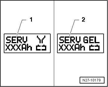
| In the display, the symbol -1-
for “Service charge for wet batteries” or symbol
-2- for “Service charge for
gel/absorbent glass mat batteries” will appear. |
| – |
Set battery capacity (Ah) of battery for charging using
respective button “Up”↑ or “Down”↓. |
| – |
Connect red terminal clamp “+” to positive terminal on
battery. |
Note
| In vehicles with start/stop function and battery monitor
control unit -J367- fitted, black terminal clamp “-” must be
connected to body earth. Connecting it to battery negative
terminal will cause start/stop system to malfunction. |
| – |
Connect black terminal clamp “-” to negative terminal. |
| The charger unit recognises the voltage required for the
connected battery (6 V, 12 V or 24 V) and initiates the charging
sequence. |
|
|
|
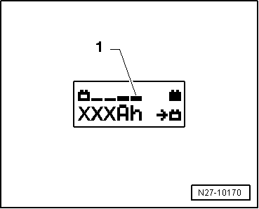
| At a charge condition of approx. 80 - 85% of the battery
voltage, the battery charger switches to the “final charge”
mode. The fourth bar appears in display
-1-. The battery is ready for use. |
Note
| The success of the “service charge” depends on the severity
of the sulphation of the battery |
| Possible faults and fault rectification: |
| 1 - |
Displayed battery voltage is not as per nominal voltage: |
| – |
Press respective button “Up”↑ or
“Down”↓ until charging sequence
starts. |
| 2 - |
Displayed battery voltage is not as per nominal voltage –
charging sequence already started: |
| – |
Press START / STOP twice. |
| – |
Press respective button “Up”↑ or
“Down”↓ until charging sequence
starts. |
| 3 - |
Battery charger does not detect a battery, when battery
voltage is less than 2 V: |
| Display remains unchanged. |
| The operating mode and ampere hours (Ah) as set are
displayed. |
| Ending battery charging sequence: |
| – |
Disconnect black terminal clamp “-” of charger from negative
terminal. |
| – |
Disconnect red terminal clamp “+” of charger from positive
terminal on battery. |
| – |
Pull charger plug out of battery charger. |
|
|
|
WARNING
Danger of injury! Observe warning notices and safety
regulations
→ Chapter!
...
WARNING
Danger of injury! Observe warning notices and safety
regulations
→ Chapter!
...
Other materials:
Using a child seat on the front passenger seat
First read and observe the introductory information
and safety warnings Not all countries allow you to transport children on
the front passenger seat. Not every child seat is suitable for use on the front
passenger seat. Volkswagen dealerships keep an up-to-date list of all authorised
chil ...
Run-flat tyres, PAX, checking
When checking a tyre, look out especially for the following
criteria:
Surface erosion or ripples on the inner side (inflation
pressure was too low or not sufficient for the load)
...
Blender
Designation:
Blender -LLS MAX 009-
Issued 10.2008
Product description
The blender -LLS MAX 009- is used to achieve homogenous
paint transitions in the blending/edge areas bet ...
© 2016-2026 Copyright www.vwgolf.org

 Charging battery with battery charger -VAS 5900-
 Charging totally discharged batteries with battery charger -VAS 5900-