Volkswagen Golf Service & Repair Manual: Adjusting Bowden cable A for entry assistance
| Special tools and workshop equipment
required |
| |
Feeler gauges -VAS 5301/10- |
-
| |
Seat pan and backrest must be padded and bolted
together. |
-
| |
Adjustment knob of backrest adjustment is turned towards
front as far as stop. |
-
| |
Bowden cable B must be attached to seat longitudinal
adjustment and to fitting on backrest. |
-
| |
Adjustment must be carried out exclusively on inner side
of seat (tunnel side). |
|
|
|
| – |
Adjust seat rail so that one locking pin
-1- protrudes. |
 Note Note
| It does not matter which of the locking pins protrudes. |
|
|

|
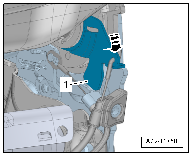
| – |
Push lever -1- on backrest
fitting in -direction of arrow- as
far as stop. |
Note
| For reasons of clarity, the padding and cover are not shown
in illustration. |
|
|
|
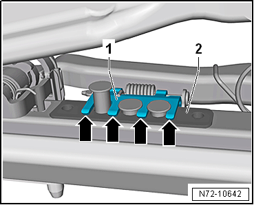
| – |
Using a feeler gauge, measure distance between tabs
-arrows- of release plate
-1- and plate
-2-. |
| |
The 0.1 mm feeler gauge must fit underneath all tabs
-arrows- of release plate. |
| |
The 0.3 mm feeler gauge must not fit underneath at least one
tab. |
| If the setting is incorrect, proceed as follows: |
|
|
|
| – |
Release Bowden cable adjuster. To do this, hold the upper
part -1- using pliers and turn
locking sleeve -2- approx. 45° in
-direction of arrow A-. |
| – |
To release locking sleeve, press it down as far as stop
-arrow B-. |
| |
The lower part -3- must be free
to turn. |
| – |
Turn lower part and upper part in opposite directions in
order to adjust Bowden cable. |
|
|

|
| – |
Adjust Bowden cable in such a way that release plate
-1- is just about to be lifted off
plate -2-. |
| |
The 0.1 mm feeler gauge must fit underneath all tabs
-arrows- of release plate. |
| |
The 0.3 mm feeler gauge must not fit underneath at least one
tab. |
| – |
Perform functional check of Bowden cables after adjusting. |
| – |
Check routing of Bowden cable or readjust Bowden cable if
locking mechanism does not release or only partially releases. |
| – |
Lock Bowden cable adjuster upon completion. |
|
|
|
Removing
–
Remove front seat
→ Chapter.
–
Secure front seat on seat repair stand
...
Removing
–
Remove front seat
→ Chapter.
–
Secure front seat on seat repair stand
...
© 2016-2026 Copyright www.vwgolf.org

 Removing and installing easy-entry Bowden cable A
 Removing and installing Bowden cable B for entry assistance