Volkswagen Golf Service & Repair Manual: Removing and installing rear side airbag crash sensor -G256-/-G257-
 WARNING
-
|
|
Observe safety instructions for
pyrotechnic components → Chapter. |
-
|
|
Before handling pyrotechnic components
(e.g. separating the electrical connector), the
person handling them must ensure that he/she is
“electrically discharged”. To do this e.g. briefly
touch the door striker plate. |
|
|
|
|
| – |
For “e-Golfs” or “Golf GTEs”, disconnect the maintenance
connector for high-voltage system -TW-. |
| – |
Disconnect battery earth cable with ignition switched on
→ Electrical system; Rep. gr.27. |
|
|
|
| – |
Remove wheel housing trim
→ Chapter. |
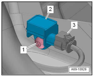
| – |
Unscrew bolt -1- and remove
crash sensor -2- for side airbag
from body. |
WARNING
| Before handling pyrotechnic components (e.g.
separating the electrical connector), the person
handling them must ensure that he/she is “electrically
discharged”. To do this e.g. briefly touch the door
striker plate. |
|
| – |
Disconnect connector -3-. |
|
|
|
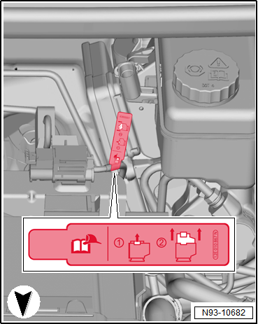
| – |
Pull out connector lock -2-,
press it down -arrow- and
disconnect connector -1- on crash
sensor. |
|
|

|
Removing
WARNING
Observe safety instructions for pyrotechnic
components
→ Chapte ...
Removing and installing seat occupied sensor, front passenger side -G128-
Note
The seat occupied sensor is only installed in the front
passenger seat.
...
Other materials:
Removing and installing turn signal switch -E2-, Kostal
Note
The turn signal switch -E2-, cruise control system switch
-E45- and intermittent wiper switch -E22- are combined to form
the steering column combination switch -E595-.
These switches cannot be separated.
...
Removing and installing injectors
Special tools and workshop equipment
required
Tool set for FSI engines -T10133 C- with -T10133/16 A- and
-T10133/19-
Removing
Risk of functional impair ...
Contents
Fig. 217 Contents of the vehicle toolkit
First read and observe the introductory information
and safety warningsThe content of the vehicle toolkit depends on the vehicle
equipment level. The following describes the maximum scope.
The vehicle toolkit contains the following
Screwdriver w ...
© 2016-2026 Copyright www.vwgolf.org

 Note
Note
 Removing and installing front airbag crash sensor, driver side -G283-
 Seat belt verification