Volkswagen Golf Service & Repair Manual: Removing and installing door opener illumination bulb -L108-/-L109-
 Note Note
| Removal and installation are described for the left side.
Removal and installation on the right side are carried out in
the same way (mirror image of left side). |
| – |
Remove front door trim panel
→ General body repairs, interior; Rep. gr.70. |
 Caution
| Risk of damage to the light conductor. |
| Touch the light conductor only at the light emitting
element in area of the interior door handle. |
|
|
|
|
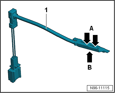
| Place fingers at indicated positions when touching the light
conductor |
| A - |
Forefinger and middle finger |
| – |
Disconnect electrical connector. |
|
|
|
| – |
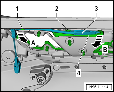
Detach light conductor -1- from
front retainer in direction of arrow -A-. |
| – |
Carefully lift light conductor -3-
slightly and swing it out of interior door handle
-4- in direction of arrow
-B-. |
| – |
Pull light conductor out of mounting
-2-. |
| Installation is carried out in the reverse sequence. |
|
|
|
Removing and installing light 2 for front door background lighting
-L203-/-L204-
Note
| The light 2 for front left door background lighting -L203-
and light 2 for front right door background lighting -L204- are
integrated in the trim strips of the door trims and cannot be
renewed individually. |
| – |
Remove trim panel from front door
→ General body repairs, interior; Rep. gr.70. |
|
|
|
| Removing and installing rear entry light
-W33-/-W34- |
Note
| Removal and installation of all entry lights are performed
in the same manner and are described only for one light. |
| The door warning lamp and the entry light are combined to
form one component. Therefore, they can only be removed and
installed together as an entire unit. |
| – |
Removing and installing entry light
→ Chapter. |
|
|
|
| Removing and installing rear door warning
lamp -W37-/-W38- |
Note
| The door warning lamp and the entry light are combined to
form one component. Therefore, they can only be removed and
installed together as an entire unit. |
| – |
Removing and installing door warning lamp
→ Chapter. |
|
|
|
Caution
Danger of damage to component surfaces.
When using leverage tools, mask visible areas of ...
Removing
Note
The selector lever position display -Y26--1-
is integrated in the selector lever gaiter and cannot be removed
...
Other materials:
Adjusting camber on rear axle, multi-link suspension
Special tools and workshop equipment
required
Torque wrench -V.A.G 1332-
Tool insert 18 mm -T10179-
...
Introduction
This chapter contains information on the following subjects:
→ Jump lead connection point (earth connection)
→ How to start the engine using jump leads
If the engine fails to start because the vehicle battery is flat, the flat battery
can be connected to the battery of another ...
Assembly overview - drive shaft, constant velocity joint VL100
1 -
Outer constant velocity joint
Renew only as complete unit
Removing
→ Anchor.
Installing: drive onto shaft to stop using plastic hammer
Checking
→ Chapter
2&nb ...
© 2016-2024 Copyright www.vwgolf.org

 Removing and installing front entry light -W31-/-W32-
 Removing and installing selector lever position display -Y26-