Volkswagen Golf Service & Repair Manual: Assembly overview - control unit and hydraulic unit, LHD vehicles
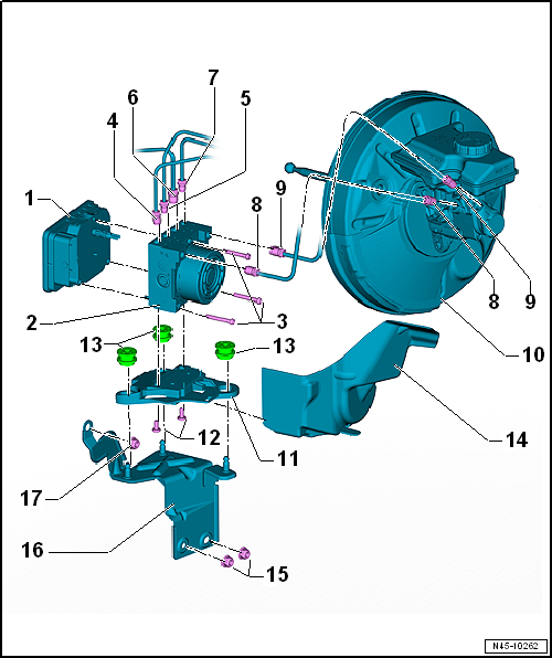
| 1 - |
ABS control unit -J104- |
| Removing and installing
→ Chapter. |
| 2 - |
ABS hydraulic unit -N55- |
| Removing and installing
→ Chapter. |
| Tighten new Torx bolts alternately in 2 stages |
| 1. stage: temporary tightening torque: 1 Nm to 1.5 Nm (to allow the
seal to settle). |
| 2. stage: final specified torque: 2.5 Nm. |
| To rear right brake caliper. |
| Identification: 5.25 mm in diameter and union nut with thread M 12 x
1 |
| To front left brake caliper. |
| Identification: 5.25 mm in diameter and union nut with thread M 10 x
1 |
| To front right brake caliper |
| Identification: 5.25 mm in diameter and union nut with thread M 12 x
1 |
| To rear left brake caliper. |
| Identification: 5.25 mm in diameter and union nut with thread M 10 x
1 |
| From primary piston circuit of brake master cylinder to hydraulic
unit. |
| Identification: 6 mm in diameter, union nut with thread M 12 x 1 |
| From secondary piston circuit of brake master cylinder to hydraulic
unit. |
| Identification: 6 mm in diameter and union nut with thread M 12 x 1 |
| Removing and installing
→ Chapter. |
| Ensure that rubber dampers of retainer are not pressed out of
bracket when installing. After installation, check that the ABS
hydraulic unit -N55- is firmly seated, or malfunction can occur. |
| Allocation
→ Electronic Parts Catalogue (ETKA). |
1 -
Brake line
From secondary piston circuit of brake master cylinder to hydraulic
unit.
Identification: 6 mm in diameter and unio ...
© 2016-2024 Copyright www.vwgolf.org


 Assembly overview - control unit and hydraulic unit, RHD vehicles