Volkswagen Golf Service & Repair Manual: Renewing bonded rubber bush for axle beam
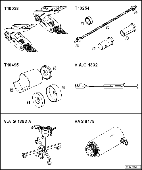
| Special tools and workshop equipment required |
| Tensioning strap -T10038- |
| Torque wrench -V.A.G 1332- |
| Engine and gearbox jack -V.A.G 1383 A--2-
with gearbox support -V.A.G 1359/2-. |
| Hydraulic press -VAS 6178- and press button -10205/13- |
| Vehicles with vehicle level sender |
|
|
|
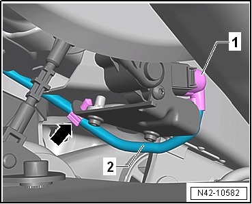
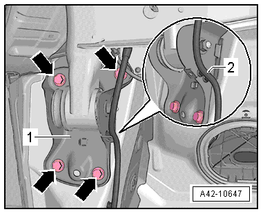
| – |
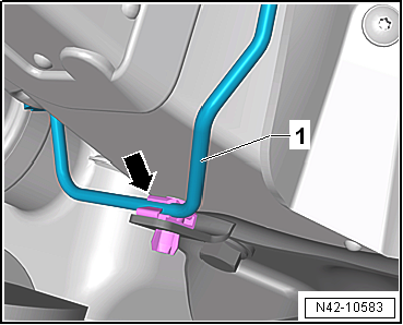
Release and pull off connector -1-
on rear left vehicle level sender -G76-. |
| – |
Unclip line -2- from clip
-arrow-. |
|
|
|
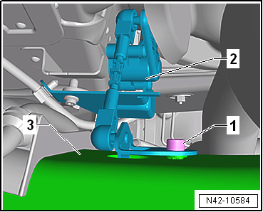
| – |
Pull rear left -G76- lever -2-
off axle beam -3-. |
| Continuation for all vehicles |
|
|
|
| – |
Unclip brake line -1- from clip
-arrow- on right mounting bracket. |
 Note Note
| The clip will be destroyed and must be renewed. |
|
|
|
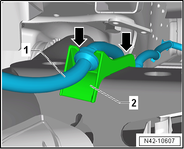
| – |
Unclip electric cable -1- from
both sides -arrows- of retainer
-2- on axle beam. |
|
|
|
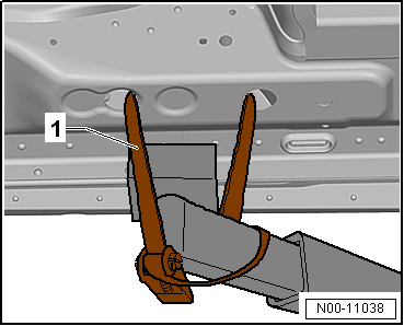
| – |
Use tensioning straps -T10038--1-
to strap vehicle to support beams of lifting platform on both
sides. |
 WARNING
| If the vehicle is not strapped down, there is a
great danger that the vehicle will slip off the lifting
platform! |
|
|
|
|
| – |
Remove bolt -1- on left and
right. |
| – |
Position engine and gearbox jack -V.A.G 1383 A- with
universal gearbox support -V.A.G 1359/2- and suitable support
underneath. |
| – |
Unclip line -2- from mounting
bracket -1-. |
| – |
Mark positions of bolts -arrows-
on mounting bracket -1- on both
sides of vehicle. |
|
|
|
| – |
Unscrew bolts -1- for right and
left axle bodies. |
|
|
|
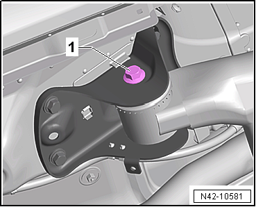
| – |
Carefully lower rear axle with engine and gearbox jack -V.A.G 1383 A-
until bolt -1- can be removed. |
|
|
|
| – |
Fit special tools as shown in illustration. |
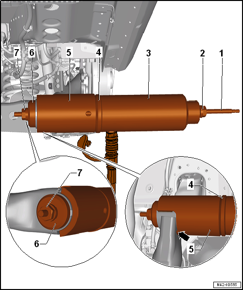
| 3 - Hydraulic press -VAS 6178- and thrust piece -T10205/13- |
| 4 - Thrust plate -T10495/3- |
| Make sure that the tube is lying against the axle beam
-arrow-. |
| 6 - Thrust piece -T10495/1- |
| – |
Pull out bonded rubber bush by operating the pump. |
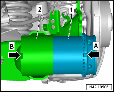
| – |
Ensure correct installation position of bonded rubber bush
-1- on axle beam
-2-. |
| Lug -arrow A- of bonded rubber
bush -1- must point towards lug
-arrow B- of axle beam
-2-. |
|
|
|
| – |
Fit special tools as shown in illustration. |
| 3 - Hydraulic press -VAS 6178- and thrust piece -T10205/13- |
| 4 - Thrust piece -T10495/1- |
| 6 - Thrust plate -T10495/3- |
| – |
Before pressing in bonded rubber bush, make sure that marking on
bonded rubber bush aligns with mark on axle beam. |
| – |
Press bonded rubber bush in to stop. |
| – |
After mounting, check installed position of bonded rubber bush. |
| Continue installation in reverse order. |
| → Chapter „Assembly overview - axle beam“ |
| → Chapter „Assembly overview - rear vehicle level sender,
torsion beam axle“ |
| → Chapter „Torque settings for wheel bolts“ |
| On vehicles with vehicle level sender, carry out basic
settings for wheel damper electronics → Vehicle
diagnostic tester. |
| On vehicles with vehicle level sender, carry out basic
adjustment of headlights
→ Electrical system; Rep. gr.94. |
|
|
|
1 -
Cover
2 -
Bolt
Renew after removing
50 Nm +45°
3 -
Bolt
...
Other materials:
Assembly overview - daytime running lights
1 -
LED module for daytime running light and side light
Left LED module for daytime running light and side light -L176-
Right LED module for daytime running light and side light -L177-
Removing and installing
→&n ...
Trailer stabilisation
First read and observe the introductory information
and safety warnings Trailer stabilisation is a subsidiary function of the
electronic stabilisation programme (ESC). The trailer stabilisation function can
detect if an attached trailer is starting to lurch from side to side.
If a lurching ...
Adapters for setting up purging circuits
The following table contains the various adapters that are
necessary to connect the air conditioner service station to the
refrigerant circuit for purposes of purging and to bridge the
removed reservoir or collector and expansion valve
(vehicle-specific) ...
© 2016-2024 Copyright www.vwgolf.org

 Assembly overview - axle beam
 Subframe