Volkswagen Golf Service & Repair Manual: Removing gearbox
| Removing gearbox, Golf 2013 ►, Golf
Estate 2014 ►, Golf SV 2015 ►, vehicles with petrol engine |
| The gearbox is removed downwards separately. |
| Remove battery, air filter and starter. The engine and
gearbox must be supported before the left subframe mounting is
removed. |
| Remove -subframe- together with
-pendulum support- and
-both suspension links-. The
-steering rack- remains installed
in the vehicle. |
| Both drive shafts are disconnected from gearbox and left
installed in wheel bearing housings. They are only swivelled to
one side and left on vehicle. |
|
|
|
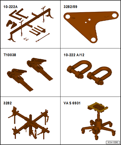
| Special tools and workshop equipment required |
| Support bracket -10 - 222 A- |
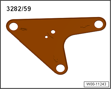
| Adjustment plate -3282/59- |
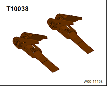
| Tensioning strap -T10038- |
| Engine and gearbox jack -VAS 6931- or -V.A.G 1383 A- |
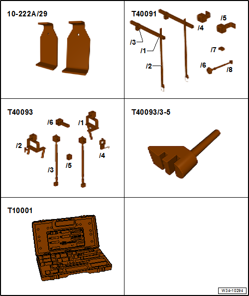
| Engine support basic set -T40091- |
| Engine support supplement set -T40093- |
| Not required: Engine support supplementary set -T40093/3-5- |
|
|
|
| Shock absorber set -T10001- |
|
|
|
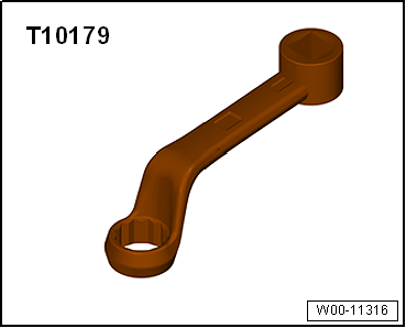
| Insert tool, 18 mm -T10179- |
|
|
|
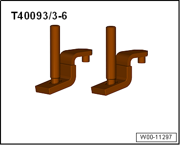
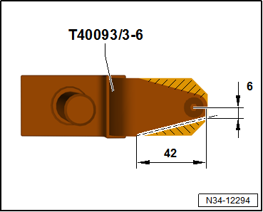
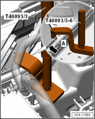
| Check adapter -T40093/3-6- and adjust as necessary
→ Fig. |
|
|
|
| Check adapter -T40093/3-6- and adjust as necessary |
| – |
If necessary, cut off the marked area. |
| – |
Round off the front edges. |
| – |
Protect adapter against corrosion. |
| – |
Then, mark adapter -T40093/3-6- with -T40093/3-6A-. |
| At a later point, support bracket -10-222 A- will be put
onto longitudinal members with adapters -T40093/3-6A-. |
| To prevent damage to longitudinal member, cover front area
of adapter -T40093/3-6A- with textile-reinforced adhesive tape
→ Electronic Parts Catalogue (ETKA chemical substances). |
| – |
Raise vehicle. All 4 supports of lifting platform must be at
same height. |
| – |
Move selector lever to position »P«. |
| – |
Remove air filter housing
→ Rep. gr.24. |
| – |
Remove battery and battery tray
→ Electrical system; Rep. gr.27. |
|
|
|
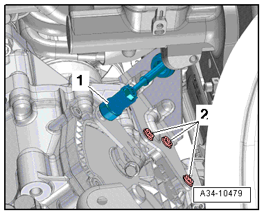
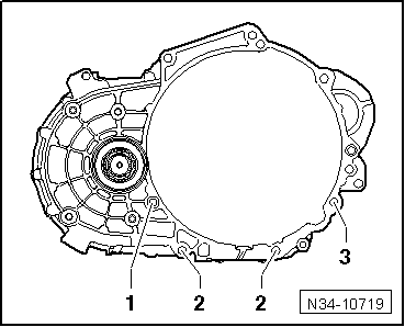
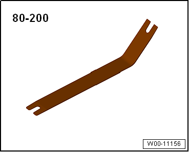
| – |
Using removal lever -80 - 200-, lever selector lever cable
-1- off gearbox selector lever. |
| – |
Remove bolts -2-, raise and tie
selector lever cable together with support bracket. |

Caution
| Risk of damage to selector lever cable. |
| Do not bend or kink selector lever cable. |
|
| – |
Remove starter
→ Electrical system; Rep. gr.27. |
| It is advisable to remove the »lower«
bolt first. |
Caution
| Risk of damaging gearbox components beyond repair. |
| Do not under any circumstances touch the contacts in
the gearbox connector by hand. Electrostatic discharge
can seriously damage the control unit and mechatronic
unit. |
|
| – |
Touch earth connection (without gloves) in order to
discharge yourself. |
|
|
|
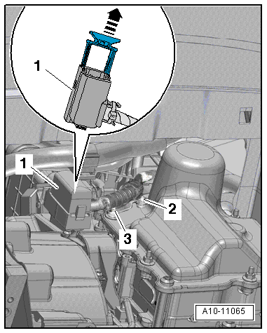
| – |
Disconnect electrical connector -1-
for mechatronic unit for dual clutch gearbox -J743-. To do this,
pull locking mechanism upwards -arrow-. |
| – |
Unscrew nuts -2- and
-3- and remove wiring retainer from
gearbox. |
| – |
Tie up wiring in area of gearbox cover. |
|
|
|
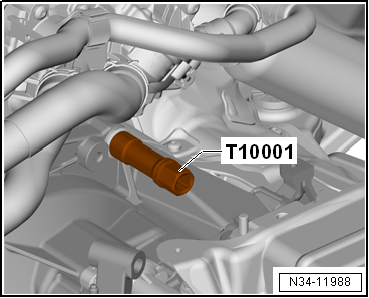
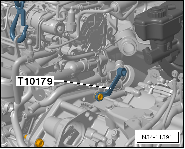
| – |
Unscrew upper engine/gearbox connecting bolts with a
suitable socket from shock absorber set -T10179- or insert tool
18 mm -T10001-. |
| – |
If there are hose and cable connections in area of engine
support eye for support bracket -10-222A-, remove these now. |
| – |
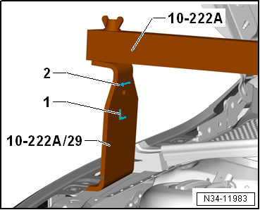
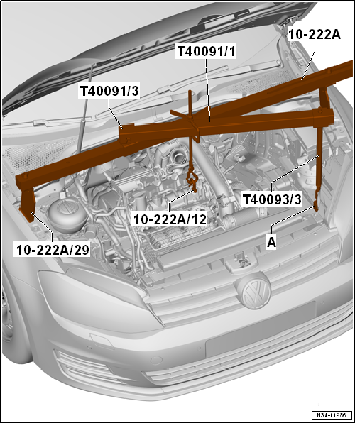
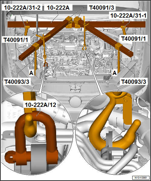
Install support bracket -10-222 A- as follows: |
| Adapter -10 - 222 A /29-, qty. 2 |
| Connecting piece -T40091/3- |
| Spindle from engine support supplement set -T40093 /3- |
|
|
|
| – |
On both sides of vehicle, insert adapters -10 - 222 A /29-
between upper wheel housing longitudinal member and mounting
plate for wing located underneath. |
| “L”-1-adapter is to be used on
“right” side of vehicle (adapter engages in recess of wing). |
| “R” (not illustrated here) adapter is to be used on “left”
side of vehicle. |
| Arrow -2- points in direction
of travel. |
|
|
|
| – |
Slide connecting piece -T40091/3- onto support bracket
-10-222 A-. |
| – |
Secure support bracket -10-222 A- to adapters -10 - 222 A
/29-. |
| -A- = adapter -T40093/3-6A- (⇒
next Fig.). |
|
|
|
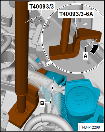
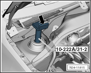
| – |
Position adapter -T40093/3-6A- on left longitudinal member
directly behind filler pipe for washer fluid reservoir. |
| The adapter -T40093/3-6A- is locked with the pins
-A- behind the web of the
longitudinal member -arrow-. |
| – |
Bolt on spindle from engine support supplement set -T40093
/3-, connect it via square tubes -T40091/1- to engine support
bracket -10-222 A- and fasten the connection (⇒ previous fig.). |
| – |
Slightly take up weight of engine/gearbox assembly on engine
support bracket -10-222 A-. |
| – |
Remove noise insulation
→ General body repairs, exterior; Rep. gr.66. |
| – |
Remove front left wheel housing liner
→ General body repairs, exterior; Rep. gr.66. |
|
|
|
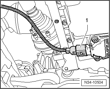
| – |
Disconnect connector -1- from
oil level and oil temperature sender -G266-. |
| – |
Remove subframe without steering rack
→ Running gear, axles, steering; Rep. gr.40. |
| – |
Disconnect both drive shafts from gearbox
→ Running gear, axles, steering; Rep. gr.40. |
|
|
|
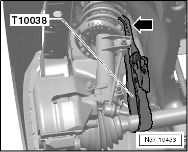
| – |
Secure drive shaft to suspension strut with tensioning strap
-T10038-. |
| The surface protection of the shafts must not be damaged. |
|
|
|
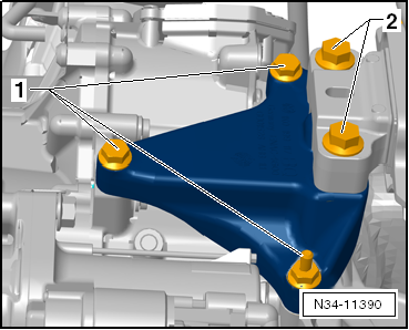
| Remove all bolts -1- and
-2- for gearbox bracket. |
|
|
|
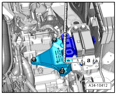
| – |
Lower engine/gearbox assembly using spindle -10 - 222 A /11-
until distance -a- is obtained
between gearbox housing and gearbox mounting. |
| – |
Remove gearbox bracket. |
| – |
Remove all connecting bolts except one which is in an easily
accessible place between engine and gearbox. |
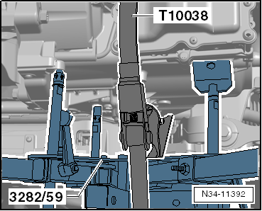
| – |
Set up gearbox support -3282- with adjustment plate
-3282/59-. |
|
|
|
| – |
Position engine and gearbox jack -VAS 6931- or -V.A.G 1383
A- under gearbox and support gearbox. Do not raise. |
| – |
Position plate of pin under gearbox housing, not under
mechatronic unit. |
| – |
Screw a pin into »rear« hole for
pendulum support. |
| – |
Secure gearbox with tensioning strap -T10038- to prevent it
from falling down. |
| The gearbox is separated from the engine in this position. |
| – |
Remove last engine/gearbox connecting bolt. |
| – |
Separate gearbox from engine,
»observing selector lever cable«. Slightly tilt gearbox
using outer spindle of gearbox support -3282-. |
|
|
|
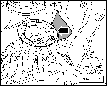
| – |
Now slightly turn gearbox and lower it. Be sure to guide
flange -1- past intermediate plate
-arrow- when lowering gearbox. |
 Note Note
| Be careful of all lines when lowering gearbox. |
| Transporting gearbox
→ Chapter. |
| Secure gearbox to assembly stand
→ Chapter. |
| Installing gearbox
→ Chapter. |
|
|
|
Removing gearbox, Golf 2013 ►, Golf Estate 2014 ►, vehicles with diesel
engine
| The gearbox is removed downwards separately. |
| Remove battery, air filter and starter. The engine and
gearbox must be supported before the left subframe mounting is
removed. |
| Remove -subframe- together with
-pendulum support- and
-both suspension links-. The
-steering rack- remains installed
in the vehicle. |
| Both drive shafts are disconnected from gearbox and left
installed in wheel bearing housings. They are only swivelled to
one side and left on vehicle. |
|
|
|
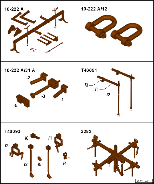
| Special tools and workshop equipment required |
| Support bracket -10-222A- |
| Support bracket -10 - 222 A /31- |
| Engine support basic set -T40091- |
| Engine support supplement set -T40093- |
| Adjustment plate -3282/59- |
|
|
|
| Tensioning strap -T10038- |
|
|
|
| Insert tool, 18 mm -T10179- |
|
|
|
| Adapter -T40093/3-6-, qty. 2 |
| Not illustrated: engine and gearbox jack -VAS 6931- or -V.A.G
1383 A- |
|
|
|
| Check adapter -T40093/3-6- and adjust as necessary |
| – |
If necessary, cut off the marked area. |
| – |
Round off the front edges. |
| – |
Protect adapter against corrosion. |
| – |
Then, mark adapter -T40093/3-6- with -T40093/3-6A-. |
| At a later point, support bracket -10-222 A- will be put
onto longitudinal members with adapters -T40093/3-6A-. |
| To prevent damage to longitudinal member, cover front area
of adapter -T40093/3-6A- with textile-reinforced adhesive tape
→ Electronic Parts Catalogue (ETKA chemical substances). |
| – |
Raise vehicle. All 4 supports of lifting platform must be at
same height. |
| – |
Move selector lever to position »P«. |
| – |
Remove engine cover panel
→ Rep. gr.10. |
| – |
Remove air filter housing
→ Rep. gr.23. |
| – |
Remove battery and battery tray
→ Electrical system; Rep. gr.27. |
|
|
|
| – |
Using removal lever -80 - 200-, lever selector lever cable
-1- off gearbox selector lever. |
| – |
Remove bolts -2-, raise and tie
selector lever cable together with support bracket. |
Caution
| Risk of damage to selector lever cable. |
| Do not bend or kink selector lever cable. |
|
| – |
Remove starter
→ Electrical system; Rep. gr.27. |
| It is advisable to remove the »lower«
bolt first. |
Caution
| Risk of damaging gearbox components beyond repair. |
| Do not under any circumstances touch the contacts in
the gearbox connector by hand. Electrostatic discharge
can seriously damage the control unit and mechatronic
unit. |
|
| – |
Touch earth connection (without gloves) in order to
discharge yourself. |
|
|
|
| – |
Disconnect electrical connector -1-
for mechatronic unit for dual clutch gearbox -J743-. To do this,
pull locking mechanism upwards -arrow-. |
| – |
Unscrew nuts -2- and
-3- and remove wiring retainer. |
| – |
Tie up wiring in area of gearbox cover. |
| – |
Remove air pipe
→ Rep. gr.21. |
|
|
|
| – |
Unscrew upper engine/gearbox connecting bolt using insert
tool 18 mm -T10179-. |
| – |
Remove noise insulation
→ General body repairs, exterior; Rep. gr.66. |
| – |
Remove lower part of front left wheel housing liner
→ General body repairs, exterior; Rep. gr.66. |
|
|
|
| – |
Disconnect connector -1- from
oil level and oil temperature sender -G266-. |
| – |
Remove subframe without steering rack
→ Running gear, axles, steering; Rep. gr.40. |
| – |
Disconnect both drive shafts from gearbox
→ Running gear, axles, steering; Rep. gr.40. |
|
|
|
| – |
Secure drive shaft to suspension strut with tensioning strap
-T10038-. |
| The surface protection of the shafts must not be damaged. |
| – |
Remove windscreen wiper arms
→ Electrical system; Rep. gr.92. |
| – |
Remove plenum chamber cover
→ General body repairs, exterior; Rep. gr.50. |
| – |
If there are hose and cable connections in area of engine
support eye for support bracket -10-222A-, remove these now. |
| – |
Install support bracket -10-222 A- as follows: |
| Adapter -10 - 222 A /31-1- |
| Adapter -10 - 222 A /31-2- |
| Connecting piece -T40091/3-, qty. 2 |
| Square tube -T40091/1-, qty. 2 |
| Spindle from engine support supplement set -T40093 /3- |
| Adapter -T40093/3-6- or adapter -T40093/3-6A--A- |
| – |
Remove caps on threaded connections for front suspension
struts. |
|
|
|
| – |
Fit adapter -10 - 222 A /31-1- and adapter -10 - 222 A
/31-2--A- onto suspension strut
mountings. |
| The webs -arrow- must face
towards front end. |
|
|
|
| – |
Slide connecting piece -T40091/3- onto support bracket
-10-222 A-. |
| – |
Bolt support bracket -10-222 A- to adapter -10 - 222 A
/31-1- and to adapter -10 - 222 A /31-2-. |
| -A- = adapters -T40093/3-6A- (⇒
next fig.). |
| On the right in direction of travel: |
| – |
Remove fuel filter and lay to side. Do not open pipe/hose
system
→ Rep. gr.20. |
|
|
|
| – |
If present, pull off wires in front area of web of
longitudinal member -arrow-. Do not
disconnect pipe/hose system. |
| – |
Place adapter -T40093/3-6A- onto right longitudinal member. |
| – |
If necessary, carefully unclip any pipes for air
conditioning system in front area. Do not disconnect pipe/hose
system
→ Heating, air conditioning; Rep. gr.87. |
| The adapter-T40093/3-6- is locked with the pins
-A- behind the web of the
longitudinal member -arrow-. |
| On the left in direction of travel: |
|
|
|
| – |
Position adapter -T40093/3-6A- on left longitudinal member
directly behind filler pipe for washer fluid reservoir. |
| The adapter -T40093/3-6A- is locked with the pins
-A- behind the web of the
longitudinal member -arrow-. |
| – |
Bolt on spindle from engine support supplement set -T40093
/3-, connect it via square tubes -T40091/1- to engine support
bracket -10-222 A- and fasten the connection (⇒ previous fig.). |
| The square tube -T40091/1- must be flush with the connecting
piece -T40091/3- and the engine support supplement set -T40093
/3- (⇒ previous illustration). |
| – |
Then attach spindles to engine support eyes. |
| – |
Take up weight of engine/gearbox assembly and support
bracket on spindles. |
|
|
|
| Remove all bolts -1- and
-2- for gearbox bracket. |
|
|
|
| – |
Lower engine/gearbox assembly using spindle -10 - 222 A /11-
until distance -a- is obtained
between gearbox housing and gearbox mounting. |
| – |
Remove gearbox bracket. |
|
|
|
| – |
Remove engine/gearbox connecting bolts
-1- and -2-. |
Note
| Loosen engine/gearbox connecting bolt
-3- and leave it installed just hand-tight. |
| – |
Set up gearbox support -3282- with adjustment plate
-3282/59-. |
|
|
|
| – |
Position engine and gearbox jack -VAS 6931- or -V.A.G 1383
A- under gearbox and support gearbox. Do not raise. |
| – |
Position plate of pin under gearbox housing, not under
mechatronic unit. |
| – |
Screw a pin into »rear« hole for
pendulum support. |
| – |
Secure gearbox with tensioning strap -T10038- to prevent it
from falling down. |
| The gearbox is separated from the engine in this position. |
| – |
Remove last engine/gearbox connecting bolt. |
| – |
Separate gearbox from engine,
»observing selector lever cable«. Slightly tilt gearbox
using outer spindle of gearbox support -3282-. |
|
|
|
| – |
Now slightly turn gearbox and lower it. Be sure to guide
flange -1- past intermediate plate
-arrow- when lowering gearbox. |
Note
| Be careful of all lines when lowering gearbox. |
| Transporting gearbox
→ Chapter. |
| Secure gearbox to assembly stand
→ Chapter. |
| Installing gearbox
→ Chapter. |
|
|
|
Install in reverse order of removal, observing the
following:
Note
Renew bolts which are tightened by turning through a
sp ...
© 2016-2024 Copyright www.vwgolf.org


 Installing gearbox