Volkswagen Golf Service & Repair Manual: Removing and installing air recirculation flap control motor -V113-, LHD
vehicles
| Heater and air conditioning system with electric/manual
controls |
| Special tools and workshop equipment
required |
| Vehicle diagnostic tester |
 Note Note
| The control motor has end stops with integrated limit
switches instead of a potentiometer. |
| First carry out the following work: |
| – |
Switch off all electrical consumers. |
| – |
Remove glove compartment
→ General body repairs, interior; Rep. gr.68. |
|
|
|
| – |
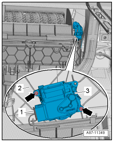
Unscrew bolts -arrows-. |
| – |
Remove air recirculation flap control motor -V113--3-
from air intake duct -2-. |
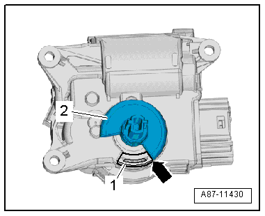
| – |
Disconnect electrical connector -1-. |
|
|
|
Special tools and workshop equipment
required
Vehicle diagnostic tester
First carry out the following work:
...
Heater and air conditioning system with electric/manual
controls
Special tools and workshop equipment
required
Veh ...
Other materials:
Removing and installing hazard warning light switch -EX3-
Removing
–
Grasp front passenger side airbag deactivated warning lamp
-K145--1- at sides
-arrows A- and pull it out of dash
panel.
–
Disconnect ele ...
Introduction
This chapter contains information on the following subjects:
→ Opening or closing the windows electrically  
→ Electric windows – functions  
→ Roll-back function for the electric windows  
Additional information and warnings:
Volkswagen information system â ...
EU tyre label, objectives
Reducing fuel consumption
Increasing road safety
Reducing traffic noise
The EU tyre label provides the end-user with important
information on the properties of the tyre. It does not
ill ...
© 2016-2024 Copyright www.vwgolf.org

 Removing and installing defroster flap control motor -V107- with
potentiometer -G135-, RHD vehicles
Removing and installing defroster flap control motor -V107- with
potentiometer -G135-, RHD vehicles Removing and installing air recirculation flap control motor -V113-, RHD
vehicles
Removing and installing air recirculation flap control motor -V113-, RHD
vehicles