Volkswagen Golf Service & Repair Manual: Preparing fibre optic cable
| Special tools and workshop equipment
required |
|
|
|
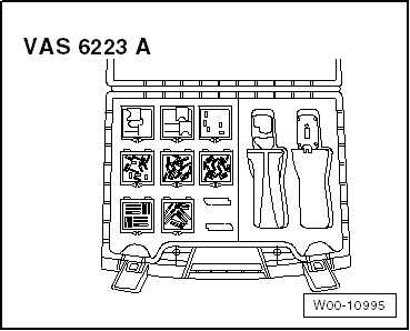
| Fibre optic cable repair kit -VAS 6223A- |
|
|
|
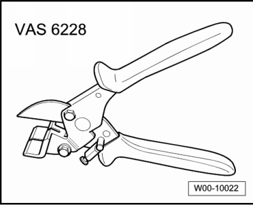
| Cutting pliers -VAS 6228- |
|
|
|
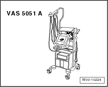
| Vehicle diagnostic tester |
 Caution
| Do not excessively bend fibre optic cables. Minimum
radius for bends is 25 mm. |
| Do not route fibre optic cables over sharp edges. |
| Make sure that the ends of fibre optic cables are
not dirty and do not grasp them with your bare hands. |
| Do not expose fibre optic cables to heat. |
| It is not permissible to twist 2 fibre optic cables
together or one fibre optic cable with a copper wire. |
| Protect connectors and connecting cables against
dust. Use protective caps from the case. |
|
|
|
|
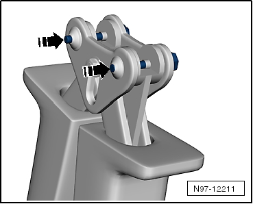
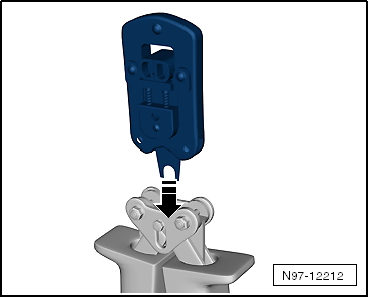
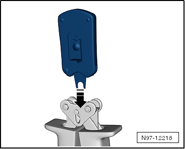
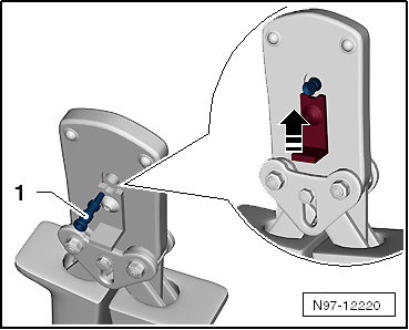
| Fit tool adapter for fibre optic cable pliers -VAS 6223/1-. |
|
|
|
| – |
Press locking pins -arrows-
out. |
| – |
Fit tool adapter onto pliers -arrow-
and press locking pins back in. |
|
|
|
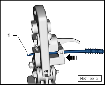
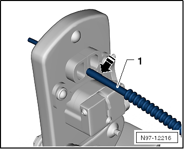
| Cutting fibre optic cable to size. |
| – |
Determine required length of fibre optic cable. |
| – |
Open fibre optic cable pliers and insert length of fibre
optic cable -1- to be cut. |
| – |
To cut the fibre optic cable to size, close fibre optic
cable pliers. |
|
|
|
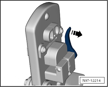
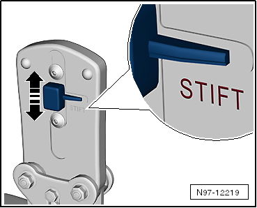
| – |
Open fibre optic cable pliers -VAS 6223/1-. |
| – |
Push down the stripping lever -arrow-. |
| – |
Insert fibre optic cable into the stripping hole. |
| The fibre optic cable must be flush with the rear of the
cutting pliers. |
|
|
|
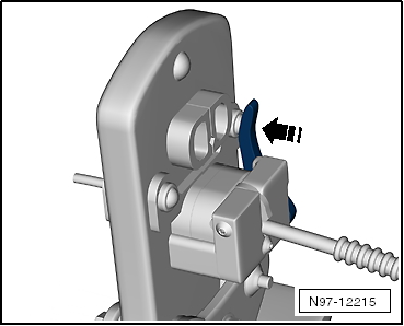
| – |
Close fibre optic cable pliers as far possible and hold
closed. |
| – |
Push the stripping lever upwards
-arrow- and remove fibre optic cable. |
|
|
|
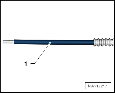
| Cut precisely (making a clean optic surface at end of
cable). |
| – |
Insert fibre optic cable -1-
into the cutting hole. |
| The insulation must be lying against the stop of the cutting
station. |
|
|
|
| – |
Close fibre optic cable pliers -VAS 6223/1- and remove
cable. |
| – |
Visually inspect cable-1- to
make sure that it has been cut correctly and that there are no
burrs on the cross-cut surface at end of cable. |
 Note Note
| Place the fibre optic cable only on surface or material that
is absolutely clean or keep it in your hand. |
| Use protective caps if there is a danger that the cross-cut
surface at the ends of the fibre optic cable will be soiled. |
|
|
|
| Fit brass pin contact to fibre optic cable. |
|
|
|
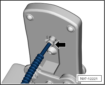
| – |
Change tool adapter -arrow-. |
| – |
Move safety catch on fibre optic cable pliers-arrow-
so that the word “Pin” can be seen. |
|
|
|
| – |
Insert a brass pin contact -1-
into the hole. |
| – |
Close locking lever on fibre optic cable pliers-arrow-. |
|
|
|
| – |
Push fibre optic cable into brass pin contact
-arrow- as far as spring-cushioned
stop and close fibre optic cable pliers. |
| – |
Open fibre optic cable pliers and remove fibre optic cable
together with brass pin contact. |
Caution
| Do not kink or excessively bend fibre optic cables
(min. bending radius 25 mm). |
|
|
|
|
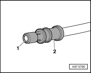
| – |
Check that the brass pin contact -2-
is correctly attached to fibre optic cable
-1-. |
| 4 crimping points must be visible on the brass connecting
pin. |
| Make sure that the brass pin contact cannot be pulled off
fibre optic cable by hand. |
| The cross-cut end surface of the fibre optic cable is
0.01 … 0.1 mm behind the brass pin contact (visual inspection). |
Note
| There are plug-in connectors that are used to connect fibre
optic cables
→ Electronic parts catalogue. |
| Installation of the new fibre optic cable in the cable
harness connector
→ Chapter. |
|
|
|
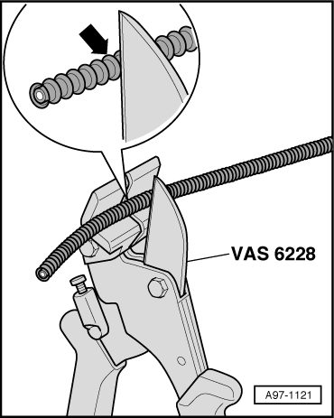
| Fitting corrugated tube onto fibre optic cable. |
| – |
Cut corrugated tube to a suitable length. |
| Use cutting pliers -VAS 6228- or a sharp knife for cutting. |
| Do not cut the corrugated tube with a paper cutter. |
| The corrugated tube must be cut at a crest
-arrow- not in a trough. |
| When the corrugated tube is installed, it must engage
audibly in the housing of the fibre optic cable. |
|
|
|
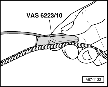
| – |
Insert fibre optic cable into pliers for fitting the
corrugated tube -VAS 6223/10- as shown in the illustration. |
| – |
Position pliers in place on the groove of the corrugated
tube. |
| – |
Push pliers in groove along the circumference of the
corrugated tube. This causes the fibre optic cable to be
inserted in the corrugated tube. |
|
|
|
Repair position with interlinked wire.
–
Place the wire to be repaired to the side at two points
(about 20 cm to both sides of the rele ...
Removing
–
Pull fibre optic cable connector off the relevant control
unit.
–
Release the locking m ...
Other materials:
Assembly overview - speed sensor on rear axle, all-wheel drive
1 -
ABS speed sensor
Clean inside surface of hole before inserting sensor
Coat inside surface with high-temperature paste -G 052 112 A3-
Removing and installing
→ Chapter
2 -
Bolt
...
Golf R - from model year 2014, sales type 5G1
Note
The specified wheel and tyre combinations apply for all the
gearboxes allocated to the respective engines.
Deviations from this are specially indicated in the table.
The Golf R will be listed according to the sales types and not by
the ...
Deactivating APP function of wiper motor
The windscreen wiper system is equipped with an APP function
(alternating park position).
With the APP function, the wiper is moved up slightly once
it has reached the lowest position. This occurs every second
time the wiper system is sw ...
© 2016-2024 Copyright www.vwgolf.org

 Wiring open circuit with two repair positions
 Detaching fibre optic cable from cable harness connector