Volkswagen Golf Service & Repair Manual: Overview of fitting locations - injection system
| Overview of fitting locations - engine compartment |
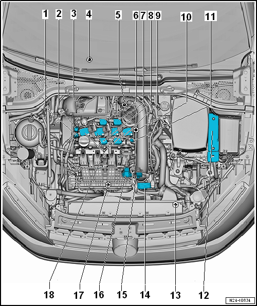
| 1 - |
Inlet camshaft control valve 1 -N205- |
| Removing and installing
→ Chapter |
| 2 - |
Exhaust camshaft control valve 1 -N318- |
| Only installed in vehicles with engine codes CPTA, CHPA, CZEA, CZDA |
| Removing and installing
→ Chapter |
| 3 - |
Lambda probe 1 before catalytic converter -GX10- |
| |
Lambda probe heater -Z19- |
| Removing and installing
→ Chapter |
| 4 - |
Lambda probe 1 after catalytic converter -GX7- |
| |
Lambda probe after catalytic converter -G130- |
| |
Lambda probe heater 1 after catalytic converter -Z29- |
| Removing and installing
→ Chapter |
| 5 - |
Charge air pressure controller -V465- |
| Removing and installing
→ Chapter |
| 6 - |
Exhaust cam actuator for cylinder 2 -N587- |
| Only installed in vehicles with engine codes CPTA, CZEA |
| Removing and installing
→ Chapter |
| 7 - |
Exhaust cam actuator for cylinder 3 -N595- |
| Only installed in vehicles with engine codes CPTA, CZEA |
| Removing and installing
→ Chapter |
| 8 - |
Inlet cam actuator for cylinder 2 -N583- |
| Only installed in vehicles with engine codes CPTA, CZEA |
| Removing and installing
→ Chapter |
| 9 - |
Inlet cam actuator for cylinder 3 -N591- |
| Only installed in vehicles with engine codes CPTA, CZEA |
| Removing and installing
→ Chapter |
| 10 - |
Hall sender 3 -G300- |
| Only installed in vehicles with engine codes CPTA, CHPA, CZEA, CZDA |
| Removing and installing
→ Chapter |
| Removing and installing
→ Chapter |
| 12 - |
Engine control unit -J623- |
| Removing and installing
→ Chapter |
| 13 - |
Radiator outlet coolant temperature sender -G83- |
| Removing and installing
→ Chapter |
| 14 - |
Throttle valve module -GX3- |
| |
Throttle valve module -J338- |
| |
Throttle valve drive for electronic power control -G186- |
| |
Throttle valve drive angle sender 1 for electronic power control
-G187- |
| |
Throttle valve drive angle sender 2 for electronic power control
-G188- |
| Removing and installing
→ Chapter |
| 15 - |
Charge air pressure sender -GX26- |
| |
Charge air pressure sender -G31- |
| |
Intake air temperature sender -G42- |
| Removing and installing
→ Chapter |
| 16 - |
Intake manifold sender -GX9- |
| |
Intake air temperature sensor 2 -G299- |
| |
Intake manifold pressure sender -G71- |
| Removing and installing
→ Chapter |
| 17 - |
Charge air cooling pump -V188- |
| Removing and installing
→ Chapter |
| 18 - |
Ignition coils with output stages |
| Ignition coil 1 with output stage -N70- |
| Ignition coil 2 with output stage -N127- |
| Ignition coil 3 with output stage -N291- |
| Ignition coil 4 with output stage -N292- |
| Removing and installing
→ Chapter |
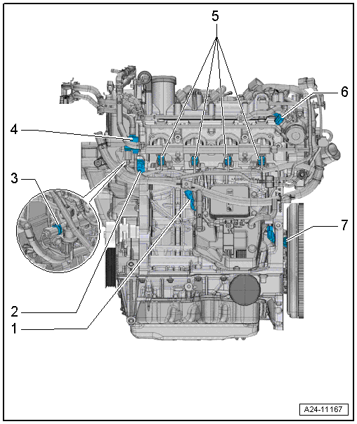
| Overview of fitting locations – engine, intake side |
| Assembly overview
→ Chapter |
| 2 - |
Oil pressure switch for reduced oil pressure -F378- |
| Assembly overview
→ Chapter |
| 3 - |
Fuel pressure sender -G247- |
| Assembly overview
→ Chapter |
| 4 - |
Activated charcoal filter solenoid valve 1 -N80- |
| Injector, cylinder 1 -N30- |
| Injector, cylinder 2 -N31- |
| Injector, cylinder 3 -N32- |
| Injector, cylinder 4 -N33- |
| Assembly overview
→ Chapter |
| 6 - |
Fuel pressure regulating valve -N276- |
| Assembly overview
→ Chapter |
| 7 - |
Engine speed sender -G28- |
| Assembly overview
→ Chapter |
| Overview of fitting locations – engine, exhaust side |
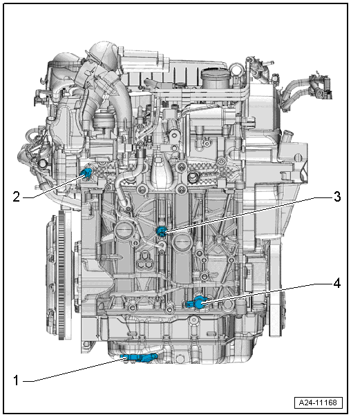
| 1 - |
Oil level and oil temperature sender -G266- |
| Removing and installing
→ Chapter |
| 2 - |
Coolant temperature sender -G62- |
| Removing and installing
→ Chapter |
| 3 - |
Oil pressure switch -F1- |
| Removing and installing
→ Chapter |
| 4 - |
Oil pressure control valve -N428- |
| Removing and installing
→ Chapter |
The fuel system is under high pressure.Risk of
injury due to fuel which may spurt out.Release high pressure.
Special tools and workshop equipment
required
...
Other materials:
Introduction
This chapter contains information on the following subjects:
→ Drink holders in the front centre console
→ Drink holders in the rear centre armrest
→ Drink holder in the rear side trim
Bottle holder
Bottle holders are located in the open stowage areas of t ...
Load-through hatch
Fig. 97 In the rear seat backrest: opening
the load-through hatch
Fig. 98 In the luggage compartment: opening
the load-through hatch
First read and observe the introductory information
and safety warnings A load-through hatch is located on the rear bench seat
behind the centre armrest. ...
Removing and installing brake pads or linings
Special tools and workshop equipment required
Vehicle diagnosis, testing and information system -VAS 5051-
Tool set for brake bleeding -VAS 6564-
Insert tool with ratchet -VAS 6784-
Bit attachment (7 mm) -T10503-
...
© 2016-2026 Copyright www.vwgolf.org

 Injection system
 Releasing high pressure in fuel system