Volkswagen Golf Service & Repair Manual: Repairing subframe
| Special tools and workshop equipment required |
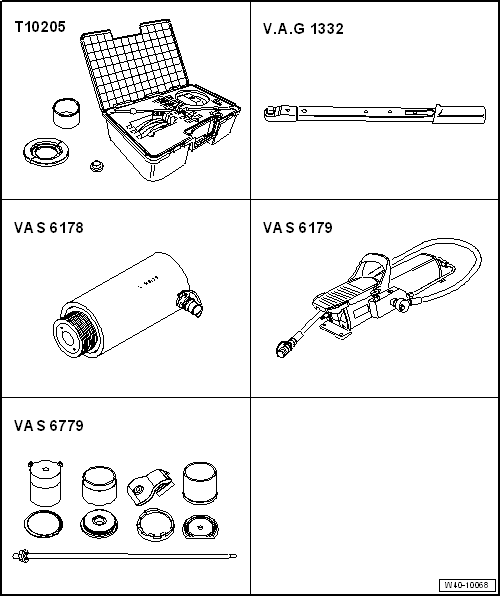
| Torque wrench -V.A.G 1332- |
| Hydraulic press -VAS 6178- |
| Renewing bonded rubber bushes for pendulum support |
| – |
If fitted, remove front noise insulation
→ General body repairs, exterior; Rep. gr.66. |
|
|
|
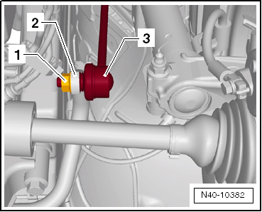
| – |
Unscrew nut -1- from coupling
rod -3- on both sides. |
| – |
Pull out coupling rod -3- from
anti-roll bar -2- on left and right
side. |
|
|
|
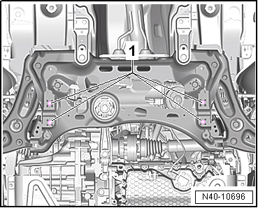
| – |
Unscrew bolts -1- for anti-roll
bar. |
| Leave the anti-roll bar in its installation position in the
vehicle. |
| – |
Remove pendulum support
→ Rep. gr.10. |
|
|
|
| Pressing out bonded rubber bush |
| – |
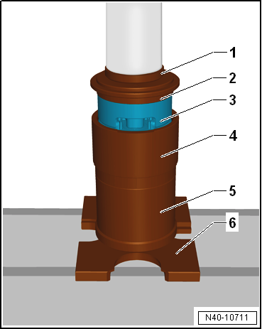
Fit assembly tool -VAS 6779- to subframe as shown in illustration. |
| – |
Place thrust piece for removal -VAS 6779-1--1-
on bonded rubber bush so that flattened side
-arrow- faces to direction of travel. |
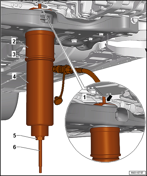
| 1 - Thrust piece for removal -VAS 6779/1- |
| 3 - Thrust piece -VAS 6779/5- |
| 4 - Hydraulic press -VAS 6178- and thrust piece -T10205/13- |
| 5 - Hexagon nut -VAS 6779/3- |
| 6 - Threaded spindle -VAS 6779/2- |
| – |
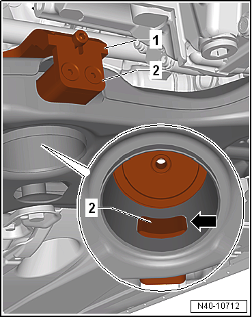
Press out both bonded rubber bushes until upper bonded
rubber bush -2- is visible in
pendulum support opening -arrow- in
subframe. |
| – |
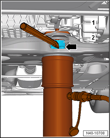
Carry out visual check of outer ring of upper bonded rubber
bush -2-. |
| If outer ring of upper bonded rubber bush
-2- is deformed, destroy it through
opening of pendulum support -arrow-
in pendulum support. |
| – |
Using a chisel or similar -1-,
create a break in the outer ring of the upper bonded rubber bush
-2-. |
 Note Note
| This process is necessary to prevent the canting of the
outer ring of the upper bonded rubber bush in the area of the
opening of the pendulum support in the subframe. |
| – |
Press out both bonded rubber bushes together. |
|
|
|
| Preparing bonded rubber bush for pressing in |
| – |
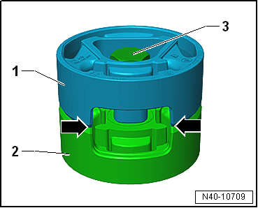
Place both bonded rubber bushes -1-
and -2- together so that the
cut-outs -arrows- line up
precisely. |
| – |
Bolt bonded rubber bushes -1-
and -2- hand-tight together using
original bolt -3-. |
|
|
|
| – |
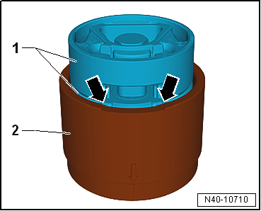
Insert bonded rubber bushes -1-
into larger diameter of tube -VAS 6779/6--2-
with bolt head facing upwards. |
| – |
Align bonded rubber bushes -1-
in tube -VAS 6779/6--2-. The
cut-out in the bonded rubber bush must align exactly with the
recess -arrow- in the tube -VAS
6779/6--2-. |
|
|
|
| – |
Press in bonded rubber bush -3-
in tube -VAS 6779/6- to stop, as illustrated. |
| 2 - |
Thrust piece -VAS 6779/5-, the side with the lettering
»A« must face upwards. |
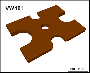
| 6 - |
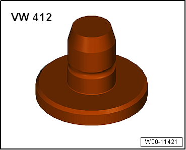
Thrust plate -VW 401- |
|
|
|
| – |
Insert counterhold -VAS 6779/7--1-
into subframe. |
| – |
Insert counterhold attachment -VAS 6779/7-1A--2-
into pendulum support opening in subframe. |
| – |
Bolt insert -VAS 6779/7-1A- to counterhold -VAS 6779/7--1-. |
| – |
Ensure that the insert -VAS 6779/7-1A--2
- is correctly seated in the pendulum support opening of
the subframe -arrow-. |
|
|
|
| Pressing in bonded rubber bush |
| – |
Screw threaded spindle -VAS 6779/2--7-
into counterhold -VAS 6779/7--1- |
| – |
Fit assembly tool -VAS 6779- to subframe as shown in illustration. |
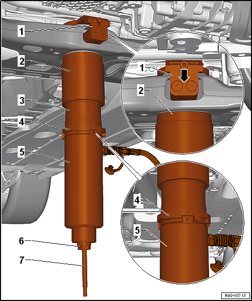
| 1 - Counterhold -VAS 6779/7- |
| 2 - Tube -VAS 6779/6-, -arrow mark- on
tube must align centrally between both bolts
-arrow-. |
| 3 - Thrust piece -VAS 6779/9- |
| 4 - Stepped ring -VAS 6779/8-, mark -I-
on stepped ring must align with mark -X- on
thrust piece -VAS 6779/9-. |
| 5 - Hydraulic press -VAS 6178- and thrust piece -T10205/13- |
| 6 - Hexagon nut -VAS 6779/3- |
| 7 - Threaded spindle -VAS 6779/2- |
| – |
Press in both bonded rubber bushes together. |
| – |
Remove assembly tool -VAS 6779- from subframe and check pressed-in
bonded rubber bushes for proper seating. |
| – |
Bolt anti-roll bar to subframe and coupling rods. |
| – |
Install pendulum support
→ Rep. gr.10. |
| – |
Install front noise insulation
→ General body repairs, exterior; Rep. gr.66. |
| → Chapter „Assembly overview - subframe“ |
| Bolts for pendulum support, except for e-Golf
→ Rep. gr.10 |
| Bolts for pendulum support, e-Golf
→ Electrical system; Rep. gr.93 |
| Bolts for noise insulation
→ General body repairs, exterior; Rep. gr.66. |
|
|
|
Special tools and workshop equipment
required
Ball joint puller -T10187-
...
Special tools and workshop equipment
required
Torque wrench -V.A.G 1332-
...
© 2016-2024 Copyright www.vwgolf.org

 Removing and installing subframe with steering rack, RHD vehicles, except
for e-Golf
Removing and installing subframe with steering rack, RHD vehicles, except
for e-Golf Removing and installing anti-roll bar