Volkswagen Golf Service & Repair Manual: Removing and installing wheel bearing housing
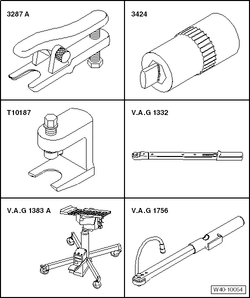
| Special tools and workshop equipment required |
| Ball joint puller -3287A- |
| Ball joint puller -T10187- |
| Torque wrench -V.A.G 1332- |
| Engine and gearbox jack -V.A.G 1383 A- |
| Angle wrench -V.A.G 1756- |
| – |
Remove bolt for drive shaft
→ Chapter. |
 Caution
| Wheel bearings must not be subjected to load after
bolt securing drive shaft to wheel hub has been
loosened. |
| If wheel bearings are loaded with weight of vehicle,
bearing will be damaged. This reduces the service life
of the wheel bearing. |
| It is not permissible to loosen drive shaft bolt
more than 90° if vehicle is standing on its wheels. |
| Do not attempt to move the vehicle without the drive
shafts fitted as this would damage the wheel bearing. If
a vehicle nevertheless has to be moved, comply with the
following: |
| Install an outer joint instead of the drive shaft. |
| Tighten outer joint to 120 Nm. |
|
| – |
Detach brake caliper and tie to body with wire
→ Brake system; Rep. gr.46. |
| – |
Remove ABS speed sensor
→ Brake system; Rep. gr.45. |
| – |
Remove brake disc
→ Brake system; Rep. gr.46 |
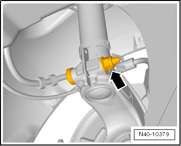
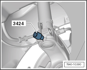
| – |
Detach bracket for brake line and electrical wiring from
wheel bearing housing and move clear. |
|
|
|
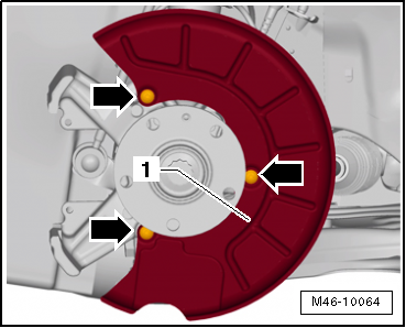
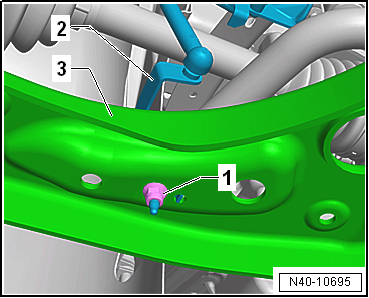
| – |
Remove splash plate -1- from
wheel bearing housing -arrows-. |
| – |
Loosen nut on track rod ball joint but do not remove
completely. |
|
|
|
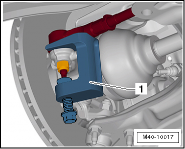
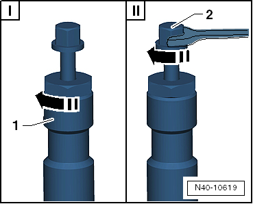
| – |
Press track rod off wheel bearing housing using ball joint
puller -T10187--1-. |
Caution
| Leave nut screwed on a few turns to protect thread
on pin. |
|
| – |
Unscrew nut, and remove track rod upwards from wheel bearing
housing. |
| Vehicles with vehicle level sender |
|
|
|
| – |
Pull bracket -2- for front left
vehicle level sender -G78- and/or for front right vehicle level
sender -G289- out of suspension link -3-,
as applicable |
| Continuation for all vehicles |
|
|
|
| – |
Pull swivel joint out of suspension link. |
| – |
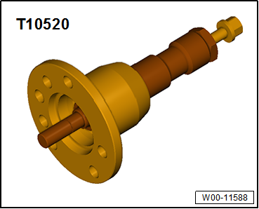
Pull outer joint of drive shaft out of wheel hub. |
| If drive shaft cannot be pulled out of the wheel bearing by
hand, use press tool -T10520-. |
|
|
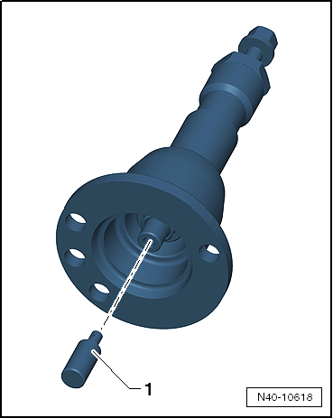
|
| Before using press tool -T10520- ensure that thrust piece
-1- is inserted. |
| Using press tool -T10520-: |
|
|
|
| – |
To be able to press out drive shaft
-3-, secure press tool -T10520--1-
to wheel hub using 3 wheel bolts -2-. |
|
|
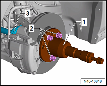
|
| – |
It is essential to follow specified sequence. |
| I - |
Tighten knurled nut -1-
hand-tight. |
| II - |
Turn only bolt -2- using a
spanner in order to press out drive shaft with press tool
-T10520-. |
 Note Note
| At the end of the procedure or for pressing out drive shaft
further the spindle must be moved to its original position in
order to deploy the hydraulic force! |
| – |
Secure drive shaft to body with wire. |
| – |
Position engine and gearbox jack -V.A.G 1383 A- under wheel
bearing housing. |
|
|
|
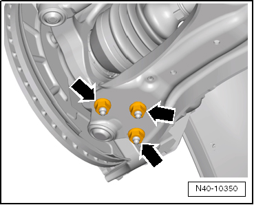
| – |
Remove threaded connection between wheel bearing housing and
suspension strut -arrow-. |
|
|
|
1 -
Splash plate
2 -
Bolt
12 Nm
3 -
Wheel bearing unit
Removing and installing
&# ...
Special tools and workshop equipment
required
Torque wrench -V.A.G 1332-
Removin ...
Other materials:
Maintaining records on refrigerant
Note
The laws and regulations listed below are valid in the
Federal Republic of Germany. Other or additional laws and
regulations may apply in other countries.
Sources in other countries may be obtained from the
...
Tyre monitoring indicator lamp
First read and observe the introductory information
and safety warnings
Lit up
Possible cause
Solution
The tyre pressure of one tyre or several tyres has decreased considerably
in comparison to the tyre pressure set by the ...
Assembly overview
Caution
If excessive force is exerted on sockets without
illumination, the retaining sleeve may be damaged.
Only illuminated sockets (cigarette lighter) can be
removed with the pull ...
© 2016-2024 Copyright www.vwgolf.org

 Assembly overview - wheel bearing assembly
 Removing and installing wheel bearing unit