Volkswagen Golf Service & Repair Manual: Removing and installing Valeo heat exchanger, RHD vehicles
| Special tools and workshop equipment
required |
|
|
|
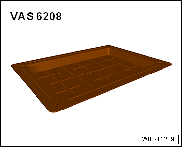
| Drip tray for workshop hoist -VAS 6208- |
|
|
|
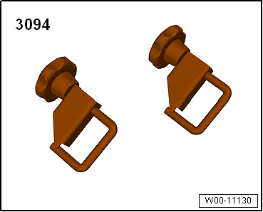
| Hose clamps up to 25 mm -3094- |
| Compressed air gun, commercially available |
|
|
|
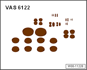
| Engine bung set -VAS 6122- |
| – |
Heed the safety precautions
→ Chapter „Safety instructions“. |
|
|
|
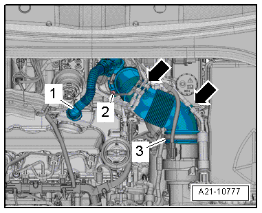
| Vehicles with TDI engine: |
| – |
Press release buttons on crankcase breather hose
-1- and detach hose from cylinder
head cover. |
| – |
Detach vacuum hoses from air pipe
-arrows- to permit access. |
| – |
Remove bolt -2-, swivel air
pipe with connection rearwards and detach from turbocharger. |
| Continuation for all vehicles: |
|
|
|
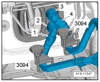
| – |
Mark installation position of coolant hoses
-1- and -4-. |
 Note Note
| The heat exchanger is designed for a particular direction of
flow of the coolant. Therefore, the coolant hoses must not be
interchanged when connecting them. |
| – |
Clamp off coolant hoses -1- and
-4- using hose clamps, up to 25 mm
-3094-. |
| – |
Lift retaining clips -2- and
-3-. |
| – |
Disconnect coolant hoses -1-
and -4- from heat exchanger for
heater. |
|
|
|
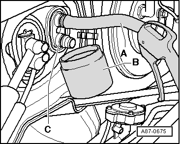
| – |
Push a piece of hose -A- onto
upper connection. |
| Insert compressed air gun into end of hose. |
| – |
Hold drip tray -B- under
connection -C- and carefully blow
coolant out of heat exchanger using compressed air gun. |
| – |
Seal off open lines and connections with clean plugs from
engine bung set -VAS 6122-. |
| – |
Remove baffle plate
→ Chapter. |
| – |
Remove glove compartment
→ General body repairs, interior; Rep. gr.68. |
| – |
Removing footwell vent on front passenger side
→ Chapter. |
| – |
Remove centre console trim in footwell
→ General body repairs, interior; Rep. gr.68. |
| – |
Vehicles with auxiliary air heater: Remove auxiliary air
heater element -Z35- with auxiliary air heater control unit
-J604-
→ Chapter. |
| – |
Cover area beneath coolant hose connections in plenum
chamber with, e.g., impermeable sheeting and absorbent paper. |
|
|
|
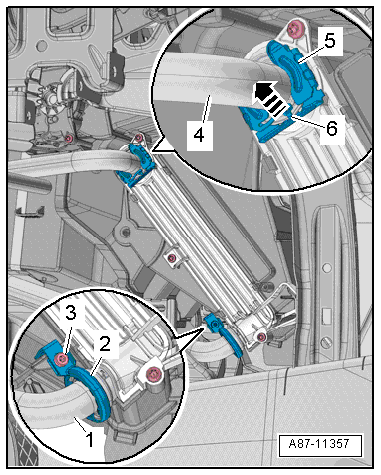
| – |
Lift locking element -6-,
remove clip -5- and pull coolant
line -4- off heat exchanger. |
Note
| The illustration shows a left-hand drive vehicle. |
| – |
Remove screw-type clip -2- and
pull coolant line -1- off heat
exchanger. |
| – |
Seal off open lines and connections with clean plugs from
engine bung set -VAS 6122-. |
|
|
|
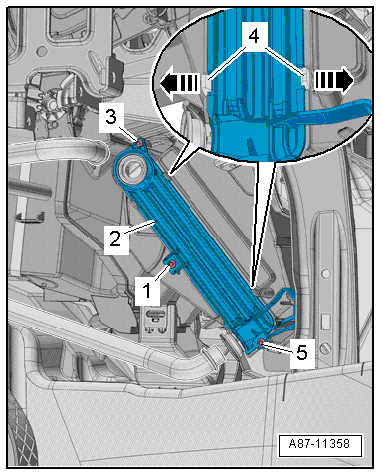
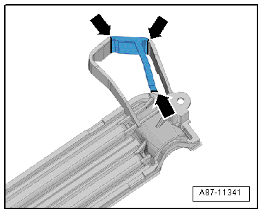
| – |
Unscrew bolts -1-,
-3- and -5-. |
Note
| The illustration shows a left-hand drive vehicle. |
| – |
Release retainer tabs -4--arrows-
and detach cover -2-. |
|
|
|
| – |
If noise insulation cannot be pulled out, cut open tabs on
cover -arrows-. |
| – |
Remove heat exchanger to left. |
| Installation is carried out in the reverse order. When
installing, note the following: |
Note
| – |
Check heater slot for dirt with heat exchanger removed. |
| – |
If necessary, remove any dirt and coolant residue. |
| – |
Vehicles with TDI engine: With auxiliary air heater element
removed, check heating element slot for dirt and clean if
necessary. |
|
|
|
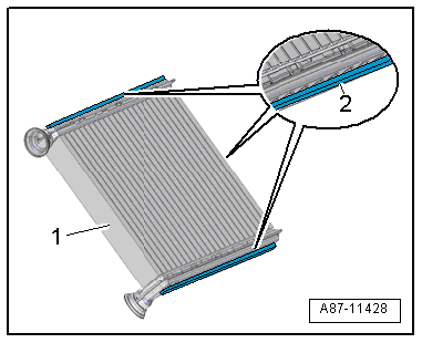
| – |
Check foam seals -2- attached
to heat exchanger -1- for damage
and replace if necessary. |
Note
| If the foam seal is not bonded in, it may roll up when the
heat exchanger is fitted. |
| Cold air may flow past the heat exchanger if the foam seal
is damaged or not properly fitted. |
|
|
|
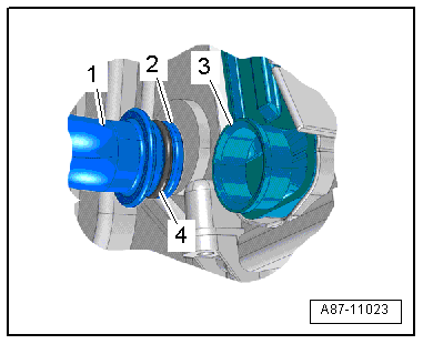
| – |
Check connection -3- of heat
exchanger and connection -2- of
coolant pipes for damage or soiling. |
| – |
Clean and smoothen sealing surface for seals. |
| – |
Moisten new seals -4- with
coolant (or lubricate lightly with silicone grease) and fit them
to coolant pipe -1-. |
| – |
Carefully slide heat exchanger into heater and air
conditioning unit to stop. |
Note
| When sliding in the heat exchanger, make sure not to damage
the connections and coolant pipes. |
| – |
Push coolant pipes into heat exchanger to stop. |
Risk of malfunction on heat exchanger due to defective seals and
leaks.Never squeeze seals.Never cant coolant pipes.Slide on coolant
pipes completely. |
|
|
| – |
Fit new clip -5- or screw-type
clip -2- onto joint of coolant pipe
and heat exchanger. |
| – |
Tighten bolt -3-
→ Chapter „Assembly overview - heater and air conditioning unit“. |
| – |
Check clip and screw-type clip for proper seating on
connections of heat exchanger and check coolant pipes. The
coolant pipes must not contact air distribution housing or any
other components. |
| – |
Fill with coolant
→ Rep. gr.19. |
| – |
Read event memory, and clear any entries displayed vehicle
diagnostic tester in “Guided fault finding” mode. |
| – |
As a final step, check operation of heater and air
conditioner. |
| → Chapter „Assembly overview - heater and air conditioning unit“ |
| Turbocharger; Assembly overview - turbocharger
→ Rep. gr.21. |
| Centre console; Assembly overview - centre console
→ General body repairs, interior; Rep. gr.68 |
| Compartments/covers; Assembly overview - glove compartment
→ General body repairs, interior; Rep. gr.68. |
|
|
|
Special tools and workshop equipment
required
Drip tray for workshop hoist -VAS 6208-
& ...
Special tools and workshop equipment
required
Drip tray for workshop hoist -VAS 6208-
& ...
Other materials:
Checking airbag securing parts after an accident
All damaged securing parts must always be renewed. It is not
permissible to bend the components back into shape or
»make them fit«
The following components must be checked after the relevant
airbag has been triggered.
...
Dimensions
Fig. 21 Dimensions
First read and observe the introductory information
and safety warnings The data in the table apply to the most basic German
model.
The specified values can vary due to different tyre and wheel sizes, if additional
equipment is fitted, for different model versions, for ...
Assembly overview - coolant temperature sender
1 -
O-ring
Renew
2 -
Radiator outlet coolant temperature sender -G83-
Removing and installing
→ Chapter
3 -
Support ring
4 -
O-ring
...
© 2016-2024 Copyright www.vwgolf.org

 Removing and installing Valeo heat exchanger, LHD vehicles
 Removing and installing Denso heat exchanger, LHD vehicles