Volkswagen Golf Service & Repair Manual: Removing and installing refrigerant shut-off valve for heater and air
conditioner unit -N541
| – |
Observe safety precautions
→ Chapter „Safety precautions when handling refrigerants“. |
| – |
Comply with notes
→ Chapter „Working on refrigerant circuit“. |
| – |
Observe safety precautions when working in the vicinity of
high-voltage components
→ Chapter „Safety precautions when working in the vicinity of
high-voltage components“. |
| – |
Observe the risk category of the high-voltage system
→ Rep. gr.00. |
| – |
Drain refrigerant circuit. |
|
|
|
| – |
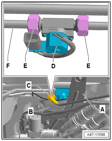
Detach bracket -A- for solenoid
valve 1 -N88- from plenum chamber bulkhead. |
|
|
|
| – |
Detach heat shield -B- in area
of -N541--D- and of refrigerant
line -F- (leading to connection on
right longitudinal member) from plenum chamber bulkhead, and
bend it back slightly. |
| – |
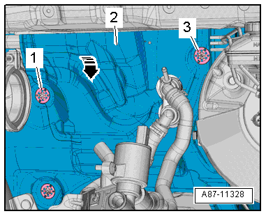
Unscrew speed nuts -1- and
-3-. |
| – |
Fold the heat shield -2- as far
forwards as necessary (and possible)
-arrow-. |
|
|
|
| – |
Disconnect connector -C- of
-N541--D-. |
Risk of freezing injury caused by escaping pressurised refrigerant.There
is a risk of injury to the skin and parts of the body due to
freezing.Always wear safety gloves.Always wear safety goggles.Extract
refrigerant, and open the refrigerant circuit immediately afterwards.If
more than 10 minutes passed since the refrigerant has been extracted, do
not open the refrigerant circuit prior to extracting refrigerant anew.
Due to re-evaporation, pressure will be built up in the refrigerant
circuit.
| – |
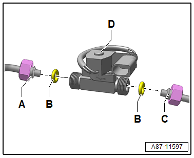
Loosen union nuts -E-.
Counterhold on -N541--D- while
doing so. |
| – |
Detach refrigerant line -F-
(leading to connection on right longitudinal member) from
retainer on plenum chamber bulkhead. |
|
|
|
| – |
Remove shut-off valve -N541--D-. |
| Installation is carried out in the reverse order. When
installing, note the following. |
 Note Note
| Following attachment, check the routing of the refrigerant
lines. They must be inserted in the retainers provided and not
make contact with any other components. |
| – |
Renew seals -B-
→ Chapter; for correct version refer to
→ Electronic Parts Catalogue. |
|
|
|
| – |
Screw on union nuts -E- to stop
by hand.
|
| – |
Secure refrigerant line -F-
(leading to connection on right longitudinal member) in retainer
on plenum chamber bulkhead. |
| – |
Tighten union nuts -E-.
Counterhold on -N541--D- while
doing so, and make sure that refrigerant lines are routed free
of stress. |
Note
| When tightening the union nuts, make sure that the
refrigerant lines remain free of stress. |
| Following attachment, check the routing of the refrigerant
lines. They must be inserted in the retainers provided and not
make contact with any other components. |
| – |
Read event memory of operating unit, Climatronic control
unit -J255-, and clear any faults which may have been stored
vehicle diagnostic tester in “Guided fault finding” mode. |
|
|
|
|
Component |
Specified torque |
| Union nuts
-E- |
16.5 Nm |
Special tools and workshop equipment
required
Torque wrench -V.A.G 1331/- (5…50 Nm)
...
Removing
–
Observe safety precautions
→ Chapter „Safety precautions when handling refrigerants“.
...
Other materials:
General information
Repair instructions for repair work on ABS
The ABS brake system is divided diagonally. The
servo-assistance is effected pneumatically by the vacuum brake
servo unit.
Vehicles with ABS are not fitted with a mechanical brake
pressure regu ...
Removing and installing charge air cooling pump -V188-
Special tools and workshop equipment
required
Hose clamps up to 25 mm -3094-
Drip tray for workshop hoist -VAS 6208-
...
Removing and installing brake pads, front brakes
Special tools and workshop equipment
required
Torque wrench -V.A.G 1331-
Piston resetting appliance -T 10145-
...
© 2016-2025 Copyright www.vwgolf.org

 Removing and installing refrigerant pressure and temperature sender -G395
 Removing and installing refrigerant shut-off valve for high-voltage battery
heat exchanger -N542
Removing and installing refrigerant shut-off valve for high-voltage battery
heat exchanger -N542