Volkswagen Golf Service & Repair Manual: Removing and installing injectors
| Special tools and workshop equipment
required |
|
|
|
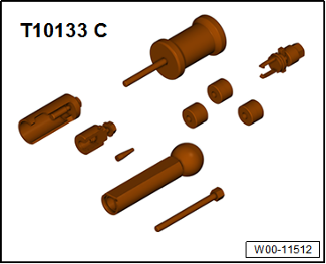
| Tool set for FSI engines -T10133 C- with -T10133/16 A- and
-T10133/19- |
| Risk of functional impairment due to soiling
→ Chapter. |
 Note Note
| Injectors must only be removed when the engine is cold. |
| – |
Remove intake manifold
→ Chapter. |
|
|
|
| – |
Removing fuel rail
→ Chapter. |
| – |
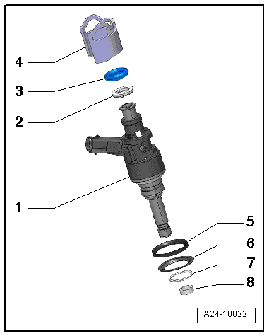
Remove O-ring -3- from injector
-1-. |
| – |
Unplug electrical connector from corresponding injector. |
|
|
|
| – |
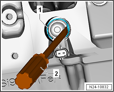
Lever support ring -1- off
injector using a screwdriver -2-. |
|
|
|
| – |
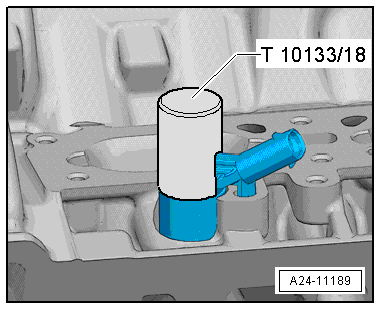
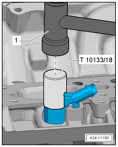
Fit impact sleeve -T10133/18- over injector. |
|
|
|
| – |
Carefully loosen injector with light blows onto impact
sleeve. |
Note
| Use a torque wrench to pull out the injector. |
| Set the torque wrench to 5 Nm. |
|
|
|
| – |
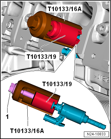
Fit puller -T10133/19- to groove on injector. |
| – |
Fit removing tool -T10133/16 A- to puller. |
| – |
Pull out injector by screwing in bolt
-1-. |
| – |
If the torque limit of »5 Nm«
has been reached and the injector still can't be pulled out,
remove the puller and use the impact sleeve again to loosen the
injector. |
| – |
Repeat the procedure on each injector. |
Note
| If the torque limit is exceeded, the injector may become
damaged. |
| The combustion chamber ring seal must always be renewed
prior to reinstalling the injector. |
| – |
Remove gasket for lower part of intake manifold. |
|
|
|
| – |
Pull support ring -4- and
spacer ring -2- off injector
-1-. |
| – |
Remove circlip -7-, upper
sealing washer -5- and lower
sealing washer -6-. |
| – |
Carefully remove old combustion chamber seal
-8-. To do this, cut the ring open
using a knife or spread the ring using a screwdriver and pull it
off towards front. |
Note
| Take care not to damage the groove of injector. The injector
must be renewed if the groove is damaged. |
|
|
|
| – |
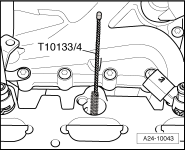
Clean hole in cylinder head using nylon brush -T10133/4-. |
Note
| Renew combustion chamber seal and O-ring. |
| Renew spacer ring if damaged. |
| – |
When reinstalling the injector, remove any combustion
residue from groove for combustion chamber ring seal and from
injector shaft using a clean cloth. |
|
|
|
| – |
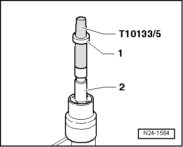
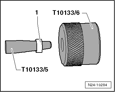
Fit assembly cone -T10133/5- with a new combustion chamber
ring seal -1- on injector
-2-. |
|
|
|
| – |
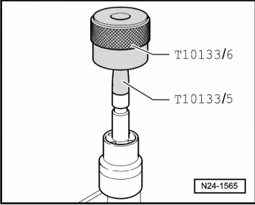
Slide combustion chamber ring seal with assembly sleeve
-T10133/6- onto assembly cone -T10133/5- as far as it will go. |
|
|
|
| – |
Turn assembly sleeve -T10133/6- around and push combustion
chamber ring seal into the respective groove. |
Note
|
|
|
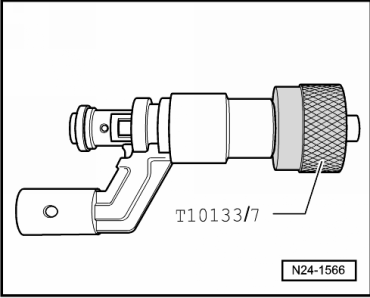
| The combustion chamber ring seal is widened when it is
pushed onto the injector. It must be compressed again after
sliding on and this is done in two stages as described below. |
| – |
Push calibration sleeve -T10133/7- onto injector as far as
stop and simultaneously turn it slightly (approx. 180°). |
| – |
Pull calibration sleeve -T10133/7- off again, turning in
opposite direction. |
|
|
|
| – |
Push calibration sleeve -T10133/8- onto injector as far as
stop and simultaneously turn it slightly (approx. 180°). |
| – |
Pull calibration sleeve -T10133/8- off again, turning in
opposite direction. |
| – |
Fit support ring -4- and spacer
ring -2- onto injector
-1-. |
|
|

|
Removing
The fuel system is under high pressure.Risk of injury due to fuel which
may spurt out.Release high pressure.
→ Chapter
...
Special tools and workshop equipment
required
Ultrasonic cleaner -VAS 6418-
Mounting plate for injection modules - ...
Other materials:
Overview of fitting locations – adaptive cruise control, variant 1
1 -
Trim for radar sensor
2 -
Adaptive cruise control unit -J428-
Removing and installing
→ Chapter
Calibrating
→ Chapter
3 -
Bolt
Qty. 2
...
General information
Repair instructions for repair work on ABS
The ABS brake system is divided diagonally. The
servo-assistance is effected pneumatically by the vacuum brake
servo unit.
Vehicles with ABS are not fitted with a mechanical brake
pressure regu ...
Stand -VAS 6873/1
Designation:
Stand -VAS 6873/1-
Product description:
Stand -VAS 6873/1- with timer
Technical data:
220-240 V, 1 OH+PE
...
© 2016-2024 Copyright www.vwgolf.org

 Removing and installing fuel rail
 Cleaning injectors