Volkswagen Golf Service & Repair Manual: Removing and installing fuel delivery unit/fuel gauge sender, vehicles with
four-wheel drive
| Special tools and workshop equipment
required |
|
|
|
| – |
Move front seats to foremost position. |
| – |
Remove rear bench seat
→ General body repairs, interior; Rep. gr.72. |
| – |
Disconnect earth wire from battery terminal
→ Electrical system; Rep. gr.27. |
| – |
If necessary, empty fuel tank
→ Chapter. |
|
|
|
| – |
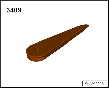
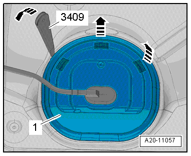
Unclip cover -1- for flange on
right at retaining tabs -arrows-,
using removal wedge -3409-. |
|
|
|
| – |
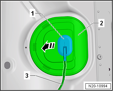
Unclip sealing grommet -1-
downwards from cover -2-. |
| – |
Push cover -2- back along
wiring harness -3-. |
The fuel system is pressurised.Risk of injury due to fuel which may
spurt out.Wear eye protection.Wear protective gloves.Release pressure:
place clean cloth around connection and carefully open connection. |
|
|
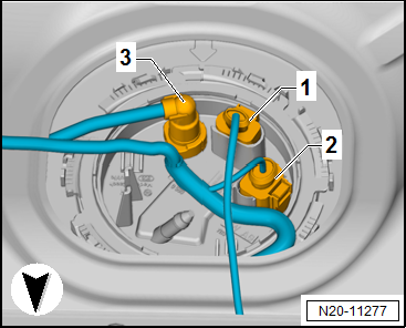
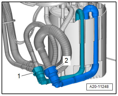
| – |
Disconnect connectors -1 and 2-
as well as fuel line -3- from
flange, and pull them off. |
| – |
If fitted, remove fuel line leading to metering pump -V54-
for auxiliary heater from sealing flange
→ Chapter. |
|
|
|
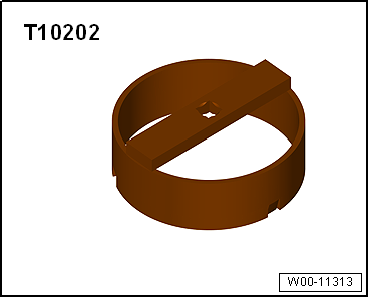
| – |
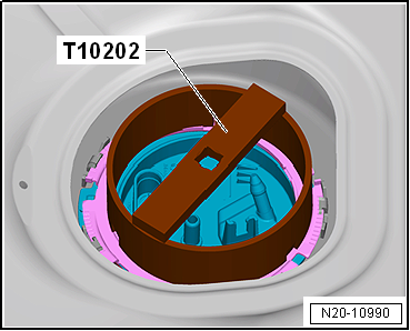
Open locking ring using wrench -T10202-. |
| – |
Carefully lift flange of fuel delivery unit. |
|
|
|
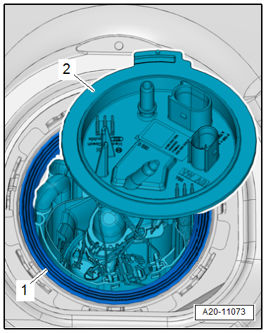
| – |
Pull right flange -2- for a
short distance out of the opening in the fuel tank. |
| – |
Remove seal -1- at the opening
in the fuel tank. |
|
|
|
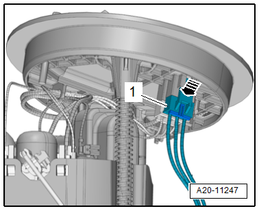
| – |
Release connector -arrow-.
Disconnect connector -1- from right
flange. |
|
|
|
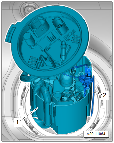
| – |
Carefully pull out fuel delivery unit
-1- with fuel gauge sender -G--2-
through opening in fuel tank by turning and tilting it as
required. |
 Note Note
| When removing the fuel delivery unit, ensure that the float
arm of the fuel gauge sender is not bent. |
| If delivery unit is to be renewed, old delivery unit must be
drained before disposal. |
| Observe environmental regulations for disposal. |
| Check fuel tank for foreign bodies and dirt. |
|
|
|
| – |
Carefully pull out fuel lines through opening in fuel tank. |
| – |
Disconnect supply line for suction-jet pump
-1- and supply line
-2-. |
| Installation is carried out in the reverse order; note the
following: |
Risk of explosion of fuel tank caused by fuel pump activation.Risk of
severe injuries and burns.If a new or completely empty fuel tank has
been installed, fill it immediately with at least 5 litres of fuel.
Note
| Push on supply line for suction-jet pump and supply line
until it engages audibly. |
| Insert new seal for fuel delivery unit dry into opening of
fuel tank. |
| When inserting fuel delivery unit, ensure that fuel gauge
sender is not bent. |
| Coat only inner side of seal with fuel. |
| Check connectors are secured properly by pulling. |
| – |
Note installation position of flange when installing
→ Fig.. |
| → Chapter „Assembly overview - fuel tank“ |
| → Chapter „Assembly overview - fuel delivery unit and fuel gauge
sender“ |
|
|
|
Special tools and workshop equipment
required
Wrench -T10202-
...
Removing
–
Observe safety precautions
→ Chapter.
–
Observe rules for cleanliness
...
© 2016-2026 Copyright www.vwgolf.org

 Removing and installing fuel delivery unit/fuel gauge sender, vehicles with
front-wheel drive
Removing and installing fuel delivery unit/fuel gauge sender, vehicles with
front-wheel drive Removing and installing fuel line for auxiliary/supplementary heater