Volkswagen Golf Service & Repair Manual: Removing and installing engine control unit -J623- (with metal locking
plate)
| Special tools and workshop equipment
required |
|
|
|
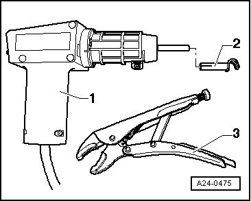
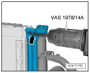
| Hot air blower -VAS 1978/14A--1-
with nozzle -2- from wiring harness
repair set -VAS 1978 B- |
| Small grinder (commercially available) |
| Vehicle diagnostic tester |
| – |
If engine control unit is renewed, select test
sequence/function Replace engine control unit on “vehicle
diagnostic tester” in “Guided functions” mode. |
| – |
Switch off ignition and remove ignition key. |
 Note Note
| If the engine control unit comes into contact with the
positive battery terminal, the engine control unit will be
destroyed. |
| Therefore, the battery must be disconnected before the
engine control unit is removed
→ Electrical system; Rep. gr.27. |
|
|
|
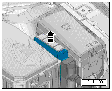
| – |
Release retaining clip -arrow-
and take out engine control unit -J623-. |
Note
| Cover the area around the engine control unit, and protect
it from flying sparks. |
|
|
|
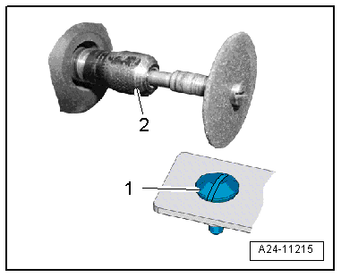
| – |
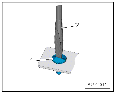
Make groove (for a screwdriver) in head of shear bolt
-1- using a small grinder
-2-. |
Note
|
|
|
| The threads of the shear bolts are secured with locking
fluid. To unscrew these bolts, the threads must therefore be
heated with the hot air blower. |
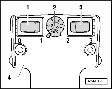
| – |
Select settings on hot air blower as shown in illustration,
i.e. set temperature potentiometer -2-
to maximum heat output and two-stage air flow switch
-3- to position 3. |
Risk of damage to adjacent components caused by hot air blower. Risk of
overheating.If necessary, cover adjacent components. |
|
|
| – |
Hold hot air blower -VAS 1978/14A- with nozzle attachment
-arrow- to thread of shear bolt and
heat thread for about 20 to 30 seconds. |
|
|
|
| – |
Unscrew shear bolt -1- using
screwdriver -2-. |
| – |
Detach metal locking plate from connectors for engine
control unit -J623-. |
| – |
Release and unplug connectors. |
| Installation is carried out in the reverse order; note the
following: |
| – |
The metal locking plate must always be re-fitted on the
engine control unit -J623-. |
| – |
Remove any locking compound residues from the threaded holes
for the shear-head bolts. Threads can be cleaned using a tap
(thread cutter). |
| – |
Use new shear-head bolts. |
| After having installed the new engine control unit, the
following work must be carried out: |
| – |
Connect battery
→ Electrical system; Rep. gr.27. |
| – |
Connect vehicle diagnostic tester. |
| – |
Switch on ignition and select the following menu options on
vehicle diagnostic tester: |
| 01 - Renew engine control unit |
|
|
|
Special tools and workshop equipment
required
Hot air blower -VAS 1978/14A--item 1-
with nozzle - ...
Other materials:
Repairs to CAN bus wiring
An unshielded two-wire line -1-
and -2- with a cross section of
0.35 mm2 or 0.5 mm2
is used for CAN bus wiring.
The colour codes of the CAN bus wiring can be gleaned from
the following table:
...
Secondary locking element
The secondary locking mechanism is a housing catch (second
line locking mechanism) that secures all the wires in one
contact housing. If a secondary locking mechanism is fitted to a
contact housing, this must always be opened or removed using the
appropr ...
Warning lamp and coolant temperature display
Fig. 194 Coolant temperature display in
instrument cluster: Ⓐ cold; Ⓑ normal; Ⓒ warning
First read and observe the introductory information
and safety warnings In normal driving conditions, the needle will be in the
middle section of the scale. The temperature may also rise when the ...
© 2016-2026 Copyright www.vwgolf.org


 Removing and installing engine control unit -J623- (with protective housing)