Volkswagen Golf Service & Repair Manual: Removing and installing defroster flap control motor -V107- with
potentiometer -G135-, LHD vehicles
| Special tools and workshop equipment
required |
| Vehicle diagnostic tester |
| First carry out the following work: |
| – |
Switch off all electrical consumers. |
| – |
Remove glove compartment
→ General body repairs, interior; Rep. gr.68. |
|
|
|
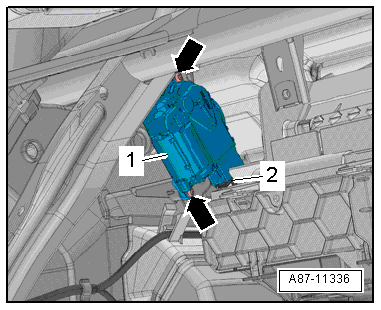
| – |
Unscrew bolts -arrows-. |
| – |
Remove defroster flap control motor -V107--1-. |
| – |
Disconnect electrical connector -2-. |
| Installation is carried out in the reverse order. When
installing, note the following: |
 Note Note
| Check operation of flaps and hinge mechanism before fitting. |
| Make sure levers and shafts are properly fitted in the
mounts. |
|
|
|
Heater and air conditioning system with electric/manual
controls
Special tools and workshop equipment
required
Veh ...
Special tools and workshop equipment
required
Vehicle diagnostic tester
First carry out the following work:
...
Other materials:
Corrosion protection for body components, add-on components and welded
components
Attachments
Wings, doors, covers and flaps must be coated completely on
the inside as well. One wet-in-wet spray pass is adequate for
this.
Before installing, add-on parts must be sealed with cav ...
Emptying fuel tank if it is less than 3/4
full
Special tools and workshop equipment required
Removal wedge -3409-
Wrench -T10202-
Torque wrench -V.A.G 1332-
Fuel extractor -VAS 5190-
Fuel extractor -VAS 5190 A- for E 85 fuel (not shown).
&nb ...
Identification plates
There are different types of identification plates.
When the auxiliary heater is replaced, check the type plate
and the duplicate plate and replace as necessary.
Identification plate on ...
© 2016-2024 Copyright www.vwgolf.org

 Removing and installing temperature flap control motor - V68-, RHD vehicles
 Removing and installing defroster flap control motor -V107- with
potentiometer -G135-, RHD vehicles
Removing and installing defroster flap control motor -V107- with
potentiometer -G135-, RHD vehicles