Volkswagen Golf Service & Repair Manual: Removing and installing control unit for daytime running light and side
light -J860-/-J861-
 WARNING
| Risk of death due to high voltage! Risk of injury
and environmental pollution! |
| Observe operation and safety notes for gas discharge
bulbs
→ Chapter. |
| It is essential that the battery earth cable is
disconnected before any work on parts of the gas
discharge headlight is performed. The parts are marked
with a yellow high voltage symbol. |
|
 Note Note
| Control unit for left daytime running light and side light
-J860- and control unit for right daytime running light and side
light -J861- are only fitted on gas discharge headlights. |
| Removal and installation are described for the left side.
Removal and installation on the right side are carried out in
the same way. |
| – |
Remove headlight
→ Chapter. |
|
|
|
| – |
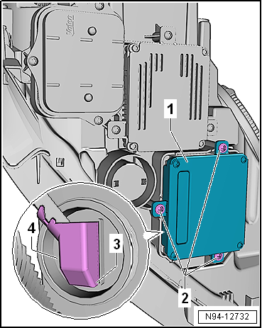
Pull control unit for left daytime running light and side
light -J860--1- off headlight. |
| – |
Disconnect electrical connector -3-. |
| Install in the reverse order of removal, observing the
following: |
 Caution
| Make sure seal is correctly seated when installing
the gas discharge bulb control unit. The ingress of
water will lead to permanent damage to the headlight. |
|
| – |
Check seal between control unit and headlight for damage. |
| → Chapter „Assembly overview - headlight“ |
|
|
|
WARNING
Risk of death due to high voltage! Risk of injury
and environmental pollution!
...
WARNING
Risk of death due to high voltage! Risk of injury
and environmental pollution!
...
Other materials:
Assembly overview - door handle and door lock
Note
Only the left side is shown. The right side is similar.
1 -
Door lock
Removing and installing
→ Chapter
2 -
Bolt
3 Nm
For lock cylinder
3 -
Mounting bracket
...
Instructions for work on underbody and stone chip protection
Note
The structure of the underbody and stone chip protection is
to be reconstructed to conform to the original condition in
appearance and thickness.
Water drainage holes must remain clear.
...
1-pack wash primer
Designation:
1-pack wash primer -LVM 044 007 A2-, light grey
1-pack wash primer -LVM 044 171 A2-, dark grey
Issued 08.2013
Product description
...
© 2016-2024 Copyright www.vwgolf.org

 Removing and installing output module for headlight -J667-/-J668-
 Removing and installing output module 2 for headlights,
»R«
Removing and installing output module 2 for headlights,
»R«