Volkswagen Golf Service & Repair Manual: Removing and installing brake master cylinder, LHD vehicles
| Special tools and workshop equipment
required |
|
|
|
| Torque wrench -V.A.G 1331- |
|
|
|
| Torque wrench -V.A.G 1410- |
| Tool inserts (11 mm) -V.A.G 1331/2- |
|
|
|
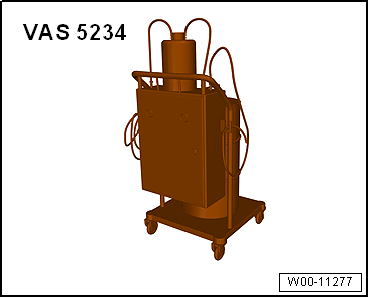
| Brake filling and bleeding equipment -VAS 5234- |
|
|
|
| Sealing plug repair kit -1H0 698 311 A- |
| – |
Observe safety precautions when working in the area of
high-voltage components
→ Chapter. |
| – |
Observe the risk classification of the high-voltage system
→ Electric drive; Rep. gr.00. |
|
|
|
| Danger to life due to high voltage |
| The high-voltage system is under high voltage. If high-voltage
components are damaged, there is a risk of severe or fatal injury due to
electric shock. |
| – |
Carry out visual inspection of high-voltage components and cables. |
| – |
Never use cutting or forming tools, or any others with sharp edges. |
| – |
Never use heat sources such as welding, soldering, thermal bonding
or hot air. |
| – |
Disconnect battery
→ Electrical system; Rep. gr.27. |
| – |
Remove power and control electronics for electric drive
-JX1-
→ Electrical system; Rep. gr.93. |
| – |
Remove bracket for power and control electronics for
electric drive -JX1-
→ Electrical system; Rep. gr.93. |
| – |
Place sufficient lint-free cloths in area of engine,
subframe and gearbox. |
| – |
Draw off as much brake fluid as possible from brake fluid
reservoir using brake filling and bleeding equipment -VAS 5234-. |
|
|
|
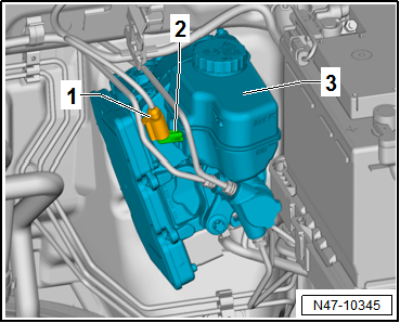
| – |
Release and pull off connector -1-
for brake fluid level warning contact -F34--2-
on brake fluid reservoir -3-. |
|
|
|
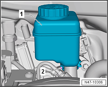
| – |
Unscrew bolt -2- and carefully
pull off brake fluid reservoir -1-
upwards. |
|
|
|
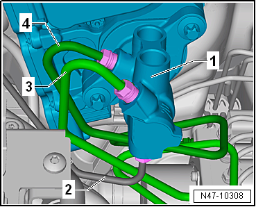
| – |
Mark position of brake lines -2 to 4-
on brake master cylinder -1-. |
| – |
Unscrew brake lines -2 to 4-
from brake master cylinder -1-. |
| – |
Seal threaded holes immediately using sealing plugs -1H0 698
311 A-. |
| – |
Fit dust caps from the bleeder valves onto brake line. |
|
|
|
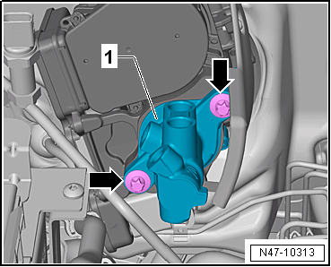
| – |
Carefully take brake master cylinder
-1- out of brake servo. |
| Install in reverse order. Note the following points: |
| – |
Thoroughly clean threaded hole for bolts
→ Item. |
| – |
When assembling brake master cylinder with brake servo, make
sure push rod is properly positioned in brake master cylinder. |
| – |
When assembling brake master cylinder with brake servo, make
sure seal
→ Item is seated correctly. |
| – |
Fit sealing plugs onto brake fluid reservoir
→ Item. |
| – |
Moisten sealing plugs
→ Item with brake fluid before pressing brake fluid
reservoir into brake master cylinder. |
| – |
Bleed brake system
→ Chapter. |
| – |
Subsequently bleeding the brake system
→ Chapter. |
| – |
Perform basic setting for electromechanical brake servo
→ Vehicle
diagnostic tester. |
| → Chapter „Assembly overview - brake servo/brake master
cylinder, LHD vehicles“ |
| → Chapter „Assembly overview – Brake system pressure accumulator
-VX70-“ |
| → Electrical system; Rep. gr.93 |
| → Electrical system; Rep. gr.27. |
|
|
|
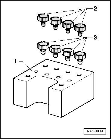
1 -
Brake system pressure accumulator -VX70-
Removing and installing
→ Chapter
2 -
Brake line
To ...
Special tools and workshop equipment
required
Torque wrench -V.A.G 1331-
...
© 2016-2024 Copyright www.vwgolf.org

 Assembly overview – Brake system pressure accumulator -VX70-, RHD vehicles
 Removing and installing brake master cylinder, RHD vehicles