Volkswagen Golf Service & Repair Manual: Removing and installing brake light switch, RHD vehicles
| Vehicle with diesel engine: |
| – |
Remove engine cover panel
→ Rep. gr.10. |
The fuel system is pressurised.Risk of injury due to fuel which may
spurt out.Wear eye pretection.Wear protective gloves.Release pressure:
place clean cloth around connection, and carefully open connection.
| – |
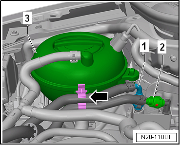
Release and pull off fuel supply lines
-1- and -2-. |
| – |
Separate plug-in connectors
→ Rep. gr.20. |
| – |
Unclip fuel lines -1- and
-2- from retainer
-arrow- on coolant reservoir
-3-. |
|
|
|
| – |
Remove securing bolts -2-. |
|
|
|
| – |
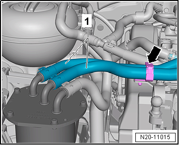
Open retainer -arrow- and
unclip fuel lines -1-. |
| – |
Then lay fuel filter to one side. |
|
|
|
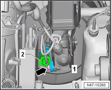
| – |
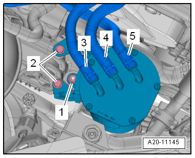
Release electrical connector -1-
and pull off. |
| – |
Release catches using a screwdriver
-arrow-. |
| – |
Place coolant expansion tank onto engine. |
| – |
Remove upper toothed belt guard
→ Rep. gr.15. |
|
|
|
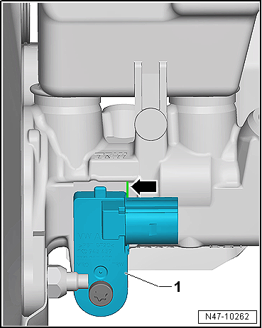
| – |
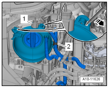
Release connector -1- and pull
off brake light switch -F--2-. |
| – |
Unscrew brake light switch -F- from brake master cylinder. |
| Install in reverse order of removal, observing the
following: |
|
|
|
| – |
Ensure that brake light switch -F--1-
seats properly on edge -arrow- of
brake master cylinder. |
| → Chapter „Assembly overview - brake servo/brake master
cylinder, RHD vehicles“ |
| Toothed belt guard
→ Rep. gr.15 |
|
|
|
Removing
Vehicles with diesel engine:
–
Remove air hose from air filter housin ...
Note
If there are problems with the brake servo, first check the
brake servo vacuum system
→ Chapter.
Special tools a ...
Other materials:
Routing and securing lines
Risk of damage to lines
Lines may become damaged by moving or hot components.
–
Route lines in their original positions.
–
Ensure that there is sufficient clearance to moving or hot
components.
...
Side airbags
Fig. 73 On the left-hand side of the vehicle:
deployment zones of side airbags (variant A). On the side of the front seat: location
and deployment range of the side airbag (variant B)
First read and observe the introductory information
and safety warnings The side airbags are located in th ...
Removing and installing coupling rod
Special tools and workshop equipment
required
Torque wrench -V.A.G 1332-
Removing
–
Raise vehicle.
...
© 2016-2024 Copyright www.vwgolf.org

 Removing and installing brake light switch, LHD vehicles
 Removing and installing brake servo, LHD vehicles