
Volkswagen Golf Service & Repair Manual: Overview of fitting locations - seals
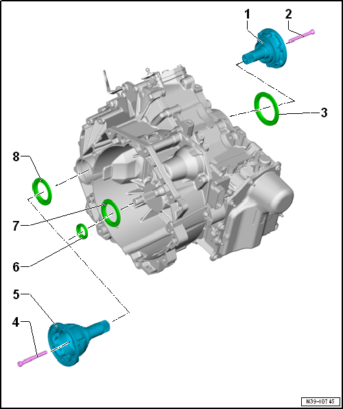
| 1 - | Left flange shaft |
| 2 - | Bolt |
| Always renew after removing. |
| 30 Nm |
| 3 - | Seal, left |
| For left flange shaft |
| Renewing → Chapter |
| 4 - | Bolt |
| Always renew after removing. |
| 30 Nm |
| 5 - | Right flange shaft or stub shaft |
| 6 - | Oil seal for inner input shaft |
| Renewing → Chapter |
| 7 - | Input shaft seal |
| Renewing → Chapter |
| 8 - | Seal, right |
| For right flange shaft |
| Renewing → Chapter |
 Oil seals
...
 Renewing left oil seal
Special tools and workshop equipment
required
Multipurpose tool -VW 771-
...
Other materials:
Removing and installing mounting bracket
Special tools and workshop equipment
required
Removing
Note
Removal and installation are only described for the left
door handle bracket. The right side is similar.
...
Schematic diagram - coolant hoses, Golf GTE
Note
Currently, only the auxiliary heater function is available.
At the moment the auxiliary heater is not intended to be
operated as a supplementary heater. In vehicles with a
high-voltage system, the high-voltage heater (PTC) -Z115- is
...
Removing and installing coolant pump for high-voltage battery -V590-
Special tools and workshop equipment
required
Hose clamps, up to 25 mm -3094-
Hose clip pliers -VAS 6362-
...
