Volkswagen Golf Service & Repair Manual: Dismantling and assembling drive shaft
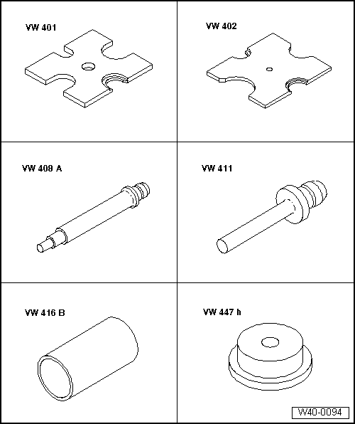
| Special tools and workshop equipment required |
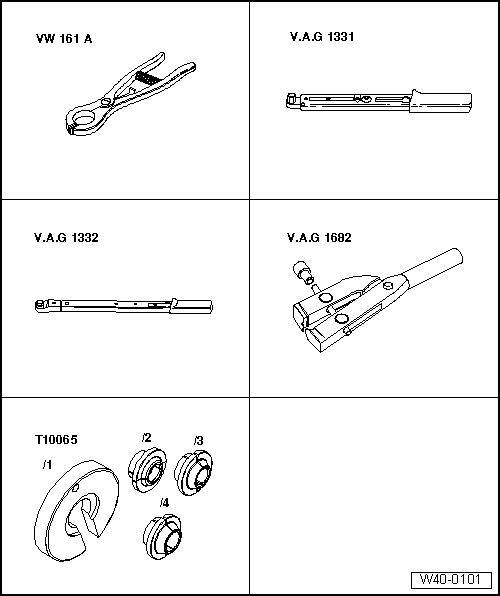
| Circlip pliers -VW 161 A- |
| Torque wrench -V.A.G 1331- |
| Torque wrench -V.A.G 1332- |
| Special pliers -V.A.G 1682- |
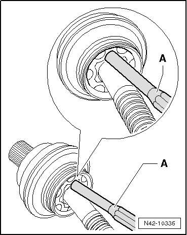
| Driving off outer constant velocity joint |
| – |
Clamp drive shaft in vice using protective jaw covers. |
| – |
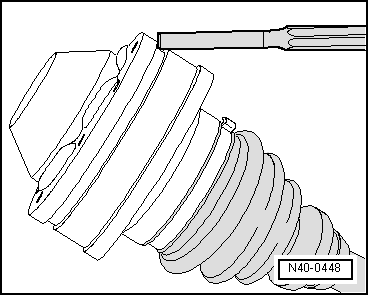
Drive constant velocity joint off drive shaft using drift
-A-. |
| Drift must be positioned exactly on ball hub of constant
velocity joint. |
|
|
|
| Installation position of dished spring at outer joint |
| – |
Use plastic-headed hammer to drive joint onto shaft until
circlip engages. |
|
|
|
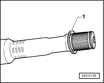
| Driving off cover for inner joint |
|
|
|
| Pressing off inner constant velocity joint |
| – |
Press off protective boot off joint using a drift. |
| – |
Remove both clamps and slide boot towards outer joint. |
|
|
|
| Installation position of dished spring at inner joint |
|
|
|
| Pressing on inner constant velocity joint |
 Note Note
| Chamfer on internal circumference of ball hub (splines) must
face contact shoulder on drive shaft. |
| – |
Press joint on to stop. |
| – |
Install retaining ring. |
|
|
|
| – |
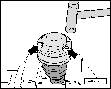
Using bolts -arrows-, align new
cover in relation to bolt holes. |
| The alignment must be very accurate, because no further
alignment is possible once the part has been hammered on. |
| – |
Drive on cover using a plastic hammer. |
|
|
|
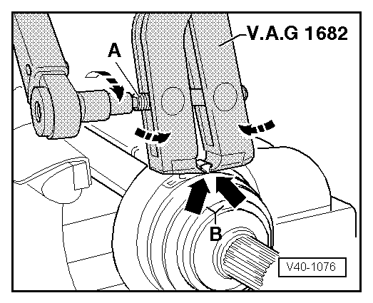
| Tighten clamp on outer joint |
| – |
Position clamp tensioner -V.A.G 1682- as shown in diagram.
Ensure jaws of tensioner lie in corners
-arrows B- of ear on O-type clip. |
| – |
Tighten clamp by turning spindle with a torque wrench (do
not cant pliers).
|
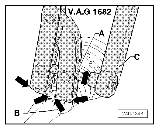
Note
| Due to the hard material of the protective boot (compared to
rubber) and the necessity of using a stainless steel clamp, it
is only possible to tension the clamp with clamp tensioner -V.A.G
1682-. |
| Use torque wrench -C - with
setting range of 5 ... 50 Nm (e.g. torque -V.A.G 1331-). |
| Make sure thread of spindle -A-
on pliers moves freely. Lubricate with MoS2 grease if necessary. |
| If the thread is tight (e.g. due to dirt), the required
clamping force for the clamp will not be attained although the
specified tightening torque is applied. |
|
|
|
| Tightening clamp on small diameter |
|
|
|
Special tools and workshop equipment
required
Torque wrench -V.A.G 1332-
...
Special tools and workshop equipment
required
Socket, 24 mm -T10361A-
...
Other materials:
Wear in middle of tyre
This wear pattern is found on the driven wheels of
high-performance vehicles that are frequently driven long
distances at high speeds.
At high speeds, centrifugal forces cause the tyre diameter
to increase more in the middle of the tread ...
Dealing with problems with Midtronics -MCR340V- battery tester
Under certain circumstances, the display may show errors or
messages according to status.
The most frequent display messages are listed below,
together with suggested solutions.
Note
For messages not liste ...
Paintwork system for plastic components
Issue 03.2010
This universal system allows simple and reliable painting of
all external plastic components in standard applications.
(Synthetic types: PP, EPDM, ABS, PC, PPO, PBTP, UP-GF, PA, PVC,
R-TPU, PUR). This technical data sheet i ...
© 2016-2024 Copyright www.vwgolf.org

 Removing and installing drive shaft
 Loosening and tightening threaded connections of drive shaft