Volkswagen Golf Service & Repair Manual: Assembly overview - fuel tank, vehicles with fuel tank leak detection
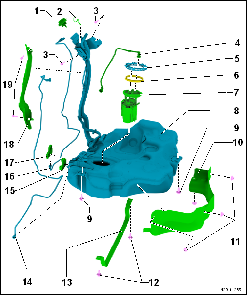
| 1 - | Cap |
| Screw in until engages audibly |
| Secured to tank flap unit by means of retaining strap. |
| 2 - | Earth connection |
| For fuel filler neck |
| 3 - | Bolt |
| Renew after removing |
| 8 Nm + 90° |
| 4 - | Fuel supply line |
| Clipped onto fuel tank |
| Do not kink |
| To pull off, press release button on connection. |
| Plug-in connectors must engage »audibly« when joined. |
| Ensure plug-in connector is secured properly by pulling it. |
| Disconnect plug-in connectors → Chapter |
| 5 - | Locking ring |
| 110 Nm |
| 6 - | Seal |
| Renew. |
| Install dry. |
| 7 - | Fuel delivery unit |
| Assembly overview → Chapter. |
| Removing and installing → Chapter. |
| With fuel gauge sender -G-. |
| Removing and installing fuel gauge sender -G- → Chapter. |
| With fuel system pressurisation pump -G6-. |
| Checking fuel system pressurisation pump -G6- → Chapter. |
| 8 - | Fuel tank |
| Removing and installing → Chapter. |
| 9 - | Bolt |
| Renew after removing |
| 20 Nm + 90° |
| 10 - | Heat shield |
| For fuel tank |
| 11 - | Panel nut |
| For heat shield. |
| 12 - | Bolt |
| Renew after removing |
| 20 Nm + 90° |
| 13 - | Securing strap |
| Ensure proper seating. |
| Mark direction of travel when removing. |
| 14 - | Breather line |
| To activated charcoal filter solenoid valve 1 -N80- |
| 15 - | Bracket |
| For control unit for fuel tank leak detection -J909-. |
| 16 - | Connecting cable |
| For control unit for fuel tank leak detection -J909-. |
| 17 - | Control unit for fuel tank leak detection -J909- |
| 18 - | Protective plate |
| 19 - | Rivets |
| For securing protective plate |
 Assembly overview - fuel tank, vehicles with front-wheel drive and torsion
beam rear suspension
Assembly overview - fuel tank, vehicles with front-wheel drive and torsion
beam rear suspension
1 -
Cap
Screw in until engages audibly
Secured to tank flap unit by means of retaining strap.
2 -
Earth connecti ...
 Assembly overview - fuel tank, vehicles with four-wheel drive
1 -
Breather line
To activated charcoal filter
Do not kink
Clipped onto fuel tank
To pull off, press rele ...
Other materials:
Removing and installing rear centre console vent duct
Note
The illustration shows a left-hand drive vehicle.
Removing
–
Remove centre console
→ General body repairs, interior; Rep. gr.68.
Note
If t ...
Removing and installing retaining plate for manually operated or automatic
anti-dazzle interior mirror, without rain and light sensor -G397- and front
camera for driver assist systems -R242
Materials
Glass-metal adhesive kit “D 000 703 A1”
Special tools and workshop equipment
required
Glass scraper (commercially available)
-1-
...
Assembly overview - impact bar
1 -
Impact bar
2 -
Guide bracket
Left and right
3 -
Hexagon nut
Qty. 2 on each side
2.0 Nm
4 -
Bolt
Qty. 2 on each side
8 Nm
5 -
Bolt ...
