Volkswagen Golf Service & Repair Manual: Assembly overview - control unit and hydraulic unit, RHD vehicles
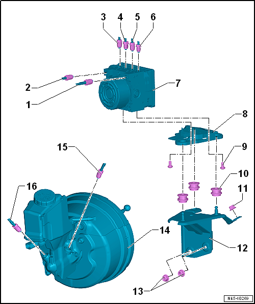
| From secondary piston circuit of brake master cylinder to hydraulic
unit. |
| Identification: 6 mm in diameter and union nut with thread M 12 x 1 |
| Repairing brake lines
→ Chapter |
| From primary piston circuit of brake master cylinder to hydraulic
unit. |
| Identification: 6 mm in diameter and union nut with thread M 12 x 1 |
| Repairing brake lines
→ Chapter |
| To rear right brake caliper. |
| Identification: 5.25 mm in diameter and union nut with thread M 12 x
1 |
| Repairing brake lines
→ Chapter |
| To front left brake caliper. |
| Identification: 5.25 mm in diameter and union nut with thread M 10 x
1 |
| Repairing brake lines
→ Chapter |
| To front right brake caliper |
| Identification: 5.25 mm in diameter and union nut with thread M 12 x
1 |
| Repairing brake lines
→ Chapter |
| To rear left brake caliper. |
| Identification: 5.25 mm in diameter and union nut with thread M 10 x
1 |
| Repairing brake lines
→ Chapter |
| 7 - |
ABS hydraulic unit -N55- with ABS control unit -J104- |
| Overview of fitting locations
→ Chapter |
| Removing and installing
→ Chapter |
| Separating ABS control unit -J104- from ABS hydraulic unit -N55-
→ Chapter |
| Attaching ABS control unit -J104- to ABS hydraulic unit -N55-
→ Chapter |
| Connecting brake line
→ Chapter |
| Check for secure seating after installing |
| Ensure that rubber dampers of retainer are not pressed out of
bracket when installing. After installation, check that the ABS
hydraulic unit -N55- is firmly seated, or malfunction can occur. |
| 14 - |
Brake servo and brake master cylinder |
| Assembly overview - brake servo/brake master cylinder
→ Chapter |
| Checking brake servo
→ Chapter |
| Removing and installing brake servo for vehicles with diesel engines
→ Chapter |
| Removing and installing brake servo for vehicles with 1.2 l and
1.4 l petrol engines
→ Chapter |
| Removing and installing brake master cylinder
→ Chapter. |
| From primary piston circuit of brake master cylinder to hydraulic
unit. |
| Identification: 6 mm in diameter and union nut with thread M 12 x 1 |
| Repairing brake lines
→ Chapter |
| From secondary piston circuit of brake master cylinder to hydraulic
unit. |
| Identification: 6 mm in diameter and union nut with thread M 12 x 1 |
| Repairing brake lines
→ Chapter |
1 -
ABS control unit -J104-
Removing and installing
→ Chapter.
2 -
ABS hydraulic unit -N55-
Remov ...
Special tools and workshop equipment required
Torque wrench -V.A.G 1331-
Torque wrench -V.A.G 1410-
Brake pedal depressor -V.A.G 1869/2- ...
© 2016-2024 Copyright www.vwgolf.org

 Assembly overview - control unit and hydraulic unit, LHD vehicles
 Removing and installing control unit and hydraulic unit, LHD vehicles,
petrol engines
Removing and installing control unit and hydraulic unit, LHD vehicles,
petrol engines