Volkswagen Golf Service & Repair Manual: Trailer socket
| The trailer socket must be connected in accordance with the
manufacturer's instructions to the electrical system of the
pulling vehicle. |
| When installing, observe the relevant current flow diagrams
and the installation instructions from the manufacturer of the
towing device. |
|
|
|
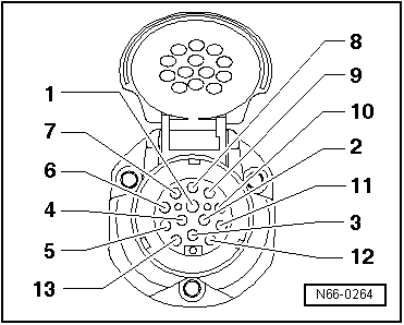
| If more than the recommended number of electrical consumers
is to be connected in a system with a
»7-pin« socket, a second »7-pin«
socket must be installed. Assignment of the pins should be
carried out in accordance with DIN ISO 1724 as follows: |
| 5 - Driving light, marker light, right number plate light |
| 7 - Driving light, marker light, left number plate light |
|
|
|
| Reversing lights, »permanent current«
and charge lead on the trailer can be used via the
»13-pin« trailer socket. If a bike
trailer or a caravan is to be towed, for example, it is
recommended that a »13-pin« trailer
socket is always used. |
|
|
|
| Assignment of the pins should then be carried out in
accordance with DIN ISO 11446 as follows: |
| 3 - Earth for current circuit 1 to 8 |
| 9 - Terminal 30 (permanent positive) |
| 10 - Terminal 15 (charge battery in trailer) |
| 13 - Earth for terminal 15/30 |
|
|
|
If the vehicle was supplied with a factory fitted towing
attachment, everything with regards to the technical and legal
requirements has already been taken care of.
...
General description:
The trailer detector control unit -J345- detects a power
consumption of at least 5 W
→ Remark when “towi ...
Other materials:
Removing and installing coolant valve for high-voltage battery -N688-
Special tools and workshop equipment
required
Hose clamps, up to 25 mm -3094-
Hose clip pliers -VAS 6362-
...
Refrigerant circuit with expansion valve
A- low-pressure side of the refrigerant circuit.
B- high-pressure side of the refrigerant circuit.
Component
Overall
state of the refrigerant
Pressure (in bar)
Temperature
in deg ...
Tyre damage
First read and observe the introductory information
and safety warnings Damage to tyres and rims is often not readily visible.
Any unusual vibrations or signs that the car is pulling
to one side may indicate that one of the tyres is damaged .
Reduce your speed immediately if you susp ...
© 2016-2024 Copyright www.vwgolf.org

 Factory fitted towing attachment
 Trailer detector control unit -J345-