Volkswagen Golf Service & Repair Manual: Supporting engine in installation position
| Special tools and workshop equipment
required |
|
|
|
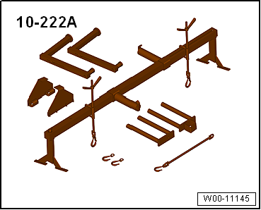
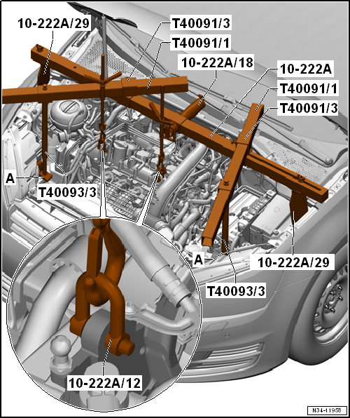
| Support bracket -10 - 222 A- |
|
|
|
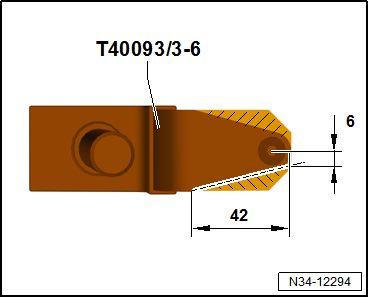
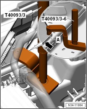
| Check adapter -T40093/3-6-, and adjust as necessary |
| – |
If necessary, cut off the marked area. |
| – |
Round off the front edges. |
| – |
Protect adapter against corrosion. |
| – |
Then, mark adapter -T40093/3-6- with -T40093/3-6A-. |
| During subsequent work process, support bracket -10-222 A-
is positioned on longitudinal members with adapters
-T40093/3-6A-. |
| To prevent damage to longitudinal members, mask off front
area of adapters -T40093/3-6A- with textile-reinforced adhesive
tape
→ Electronic Parts Catalogue (ETKA chemical substances)
. |
|
|
|
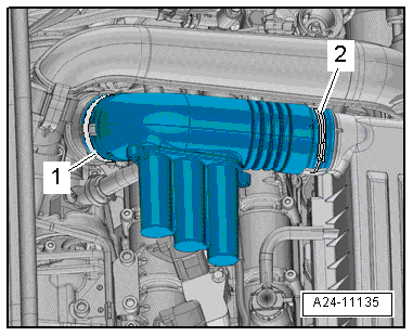
| – |
Release hose clips -1- and
-2-, and remove air pipe. |
| – |
Remove air filter housing
→ Chapter „Removing and installing air filter housing“. |
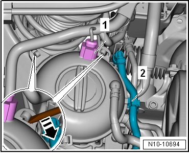
| – |
Disconnect electrical connector -1-. |
|
|
|
| – |
Move clear hose -2- from
activated charcoal filter. |
| – |
Using a screwdriver, release fasteners
-arrow- and move coolant expansion tank to one side. |
|
|
|
| – |
Fit adapter -T40093/3-6A- to longitudinal member on both
sides. |
| – |
Pins -A- must be seated behind
edges -arrow-. |
|
|
|
| – |
Fit engine support bracket -10 - 222 A- as shown in
illustration. |
| – |
Tighten spindle slightly to take up weight of engine/gearbox
assembly; do not lift. |
|
|
|
1 -
Bolt
Renew
Tightening sequence → Fig.
2 -
Engine support
Specified torque and ti ...
Removing
–
Disconnect electrical connector -1-.
–
Move clear hos ...
© 2016-2024 Copyright www.vwgolf.org

 Assembly overview - assembly mountings
 Removing and installing engine mountings