Volkswagen Golf Service & Repair Manual: Removing and installing wheel bearing housing, multi-link suspension,
four-wheel drive
| Special tools and workshop equipment
required |
|
|
|
| Torque wrench -V.A.G 1332- |
|
|
|
| Engine and gearbox jack -V.A.G 1383 A- |
| – |
Loosen outer drive shaft threaded connection
→ Chapter. |
 Caution
| Wheel bearings must not be subjected to load after
bolt securing drive shaft to wheel hub has been
loosened. |
| If wheel bearings are loaded with weight of vehicle,
bearing will be damaged. This reduces the service life
of the wheel bearing. |
| It is not permissible to loosen drive shaft bolt
more than 90° if vehicle is standing on its wheels. |
| Do not attempt to move the vehicle without the drive
shafts fitted as this would damage the wheel bearing. If
a vehicle nevertheless has to be moved, comply with the
following: |
| Install an outer joint instead of the drive shaft. |
| Tighten outer joint to 120 Nm. |
|
| – |
Remove wheel bearing unit
→ Chapter |
| – |
Remove heat shield
→ Brake system; Rep. gr.46. |
| – |
Remove spring
→ Chapter. |
| Vehicles with vehicle level sender |
|
|
|
| – |
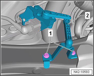
Remove retainer for rear left vehicle level sender-2-. |
| Vehicles with stone guard |
|
|
|
| – |
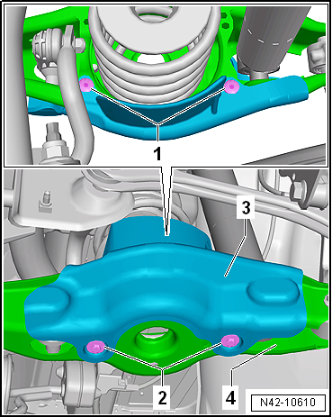
Remove spreader rivet -1-. |
| – |
Unscrew bolts -2- for stone
deflector -3-. |
| Continuation for all vehicles |
| – |
Disconnect electrical connector from ABS speed sensor and
electromechanical parking brake motor. |
|
|
|
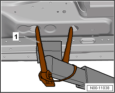
| – |
Use tensioning straps -T10038--1-
to strap vehicle to support beams of lifting platform on both
sides. |
 WARNING
| If the vehicle is not strapped down, there is a
great danger that the vehicle will slip off the lifting
platform! |
|
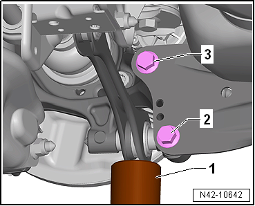
| – |
Position engine and gearbox jack -V.A.G 1383 A--1-
under track rod and press upwards slightly. |
|
|
|
| – |
Unscrew bolts -2- and
-3- one after the other. |
|
|
|
| – |
Remove engine and gearbox jack -V.A.G 1383 A--1-
from under track rod. |
|
|
|
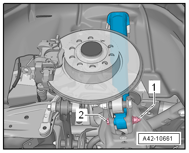
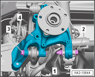
| – |
Unscrew nut -1- and remove bolt
-2-. |
|
|
|
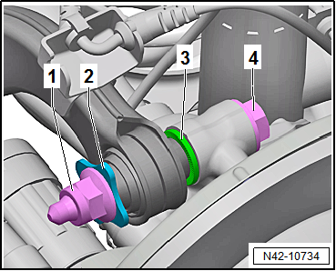
| – |
Unscrew nut -1- and pull out
bolt -2-. |
| – |
Take out wheel bearing housing -4-. |
| Install in reverse order of removal, observing the
following: |
| It is essential to follow specified sequence of work steps
below! |
| – |
Fit wheel bearing housing. |
|
|
|
| – |
Insert bolt -4- with washer
-3-. |
| – |
Only hand-tighten nut -1-. |
|
|
|
| – |
Insert bolt -2- and tighten nut
-1- only hand-tight. |
| – |
Insert bolt -3- and tighten
only hand-tight. |
|
|
|
| – |
Position engine and gearbox jack -V.A.G 1383 A--1-
under track rod and press upwards slightly. |
| – |
Screw in bolts -2- and
-3- by hand. |
| – |
Remove engine and gearbox jack -V.A.G 1383 A--1-
from under track rod. |
| – |
Install wheel bearing unit
→ Chapter |
| – |
Install heat shield
→ Brake system; Rep. gr.46. |
| The threaded connections of the wheel bearing housing may
only be loosened and tightened in the unladen weight position
→ Chapter. |
|
|
|
| – |
Detach engine and gearbox jack -V.A.G 1383 A- with support
-T10149- from wheel hub. |
|
|
|
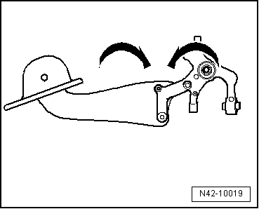
| Do not tighten bolts securing trailing arm to wheel bearing
housing until all other suspension components (especially spring
and shock absorber) on that side are fitted. To tighten, wheel
suspension must be in extended position. Only then do trailing
arm and wheel bearing housing move to the necessary position
-arrows-. |
| – |
Install coil spring
→ Chapter. |
|
|
|
| – |
Tighten bolts -2- and
-3-. |
| → Chapter „Assembly overview - suspension, multi-link
suspension, four-wheel drive“ |
| → Chapter „Assembly overview - suspension strut, shock absorber,
spring, multi-link suspension“ |
| → Chapter „Assembly overview - trailing arm“ |
| → Chapter „Assembly overview - track rod“ |
| → Chapter „Assembly overview - rear vehicle level senders,
multi-link suspension, front-wheel drive“ |
| → Chapter „Loosening and tightening threaded connections of
drive shaft“ |
| → Chapter „Torque settings for wheel bolts“ |
| Bolts for heat shield, brake caliper and brake disc
→ Brake system; Rep. gr.46 |
| On vehicles with vehicle level sender, carry out basic
settings for wheel damper electronics → Vehicle
diagnostic tester. |
| On vehicles with vehicle level sender, carry out basic
adjustment of headlights
→ Electrical system; Rep. gr.94. |
|
|
|
Special tools and workshop equipment
required
Torque wrench -V.A.G 1332-
...
Special tools and workshop equipment required
Fitting sleeve -3241/4-
Hub grease cap puller -VW 637/2-
Torque wrench -V.A.G 1332-
...
Other materials:
Searching for leaks in refrigerant circuits using leak detector -V.A.G 1796
Note
Small leaks can be detected with, for example, an electronic
leak detector.
–
Evacuate refrigerant circuit using an air conditioner
service station
→ Chapter.
Note
...
Windscreen wiper lever
Fig. 86 Operating the front windscreen
wiper
Fig. 87 Operating the rear window wiper
First read and observe the introductory information
and safety warnings
Move the lever into the required position :
Ⓐ
Switches off th ...
Connection diagram - activated charcoal filter
Note
Fuel tank leak detection takes advantage of the fact that a
vacuum develops naturally in the fuel system as the fuel in the
tank cools. The variables temperature and pressure are necessary
for fuel tank leak detection. The temperature senso ...
© 2016-2024 Copyright www.vwgolf.org

 Removing and installing wheel bearing housing, multi-link suspension,
front-wheel drive
Removing and installing wheel bearing housing, multi-link suspension,
front-wheel drive Removing and installing wheel bearing unit, torsion beam axle