Volkswagen Golf Service & Repair Manual: Removing and installing sealing flange on gearbox side
| Special tools and workshop equipment
required |
|
|
|
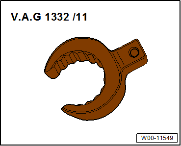
| Flared ring spanner tool insert AF 24 -V.A.G 1332/11- |
|
|
|
| – |
Remove flywheel
→ Chapter. |
|
|
|
| – |
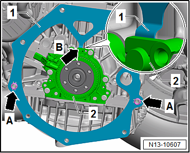
Remove intermediate plate -1-
from dowel sleeves -arrows A-. |
| – |
Guide intermediate plate -1-
upwards. |
| – |
While doing so, pull retaining lug
-arrow B- of intermediate plate -1-
out of recess behind sealing flange. |
| Setting crankshaft to “TDC” position: |
| – |
Remove ignition coil with output stage for cylinder 1
→ Chapter. |
| – |
Remove spark plug from cylinder 1. |
| Setting correct position of crankshaft for screwing in
locking pin: |
|
|
|
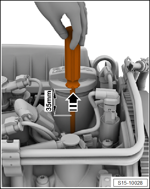
| – |
Carefully insert a screwdriver with a shaft length of at
least 250 mm in -direction of arrow-
into spark plug hole so that it contacts piston crown. |
| – |
Turn crankshaft in direction of engine rotation to “BDC” for
no. 1 cylinder. |
|
|

|
| – |
Turn crankshaft further in direction of engine rotation,
until screwdriver has moved 35 mm upwards in
-direction of arrow-. |
|
|
|
| – |
Unscrew plug for “TDC” hole in cylinder block
→ Fig.. |
| – |
Unscrew plug for “TDC” hole in cylinder block. |
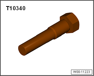
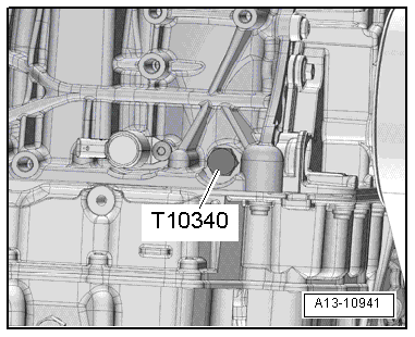
| If locking pin -T10340- cannot be screwed in as far as stop,
this indicates that crankshaft is not in the correct position! |
| In this case, proceed as follows: |
| Turn crankshaft 90° in direction of engine rotation. |
| Screw locking pin -T10340- into cylinder block as far as
stop and tighten to 30 Nm. |
| Turn crankshaft in direction of engine rotation as far as
stop. |
| – |
Screw locking pin -T10340- into cylinder block as far as
stop and tighten to 30 Nm. |
| – |
Rotate crankshaft in normal direction of rotation as far as
stop. |
| The locking pin now rests against the crank web. |
 Note Note
| Locking pin -T10340- locks crankshaft in direction of engine
rotation only. |
| – |
Remove sump (bottom section)
→ Chapter „Removing and installing lower part of sump“. |
| – |
Remove upper part of sump
→ Chapter „Removing and installing upper part of sump“. |
| – |
Remove engine speed sender -G28-
→ Chapter. |
|
|
|
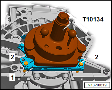
| – |
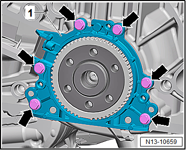
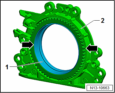
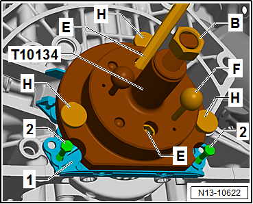
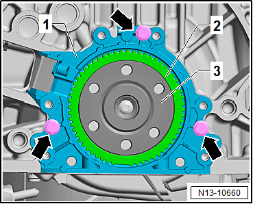
Unscrew bolts -arrows- for
sealing flange -1-. |
|
|
|
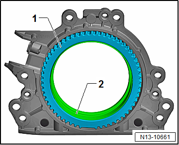
| The sealing flange with a PTFE seal is equipped with a
sealing lip support ring -2-. This
support ring serves as a fitting sleeve and must not be removed
prior to installation. |
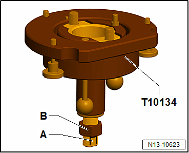
| Sealing flange and sender wheel -1-
must not be separated or turned after removal from packaging. |
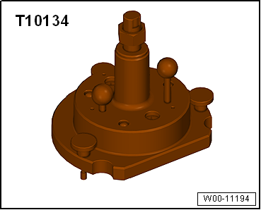
| The sender wheel -1- is held in
its installation position on the locating pin of the assembly
tool -T10134-
→ Anchor. |
| Sealing flange and oil seal form one unit and must only be
renewed together with the sender wheel. |
| The assembly tool -T10134- is held in its position relative
to the crankshaft by a guide pin inserted into a hole in the
crankshaft
→ Anchor. |
|
|
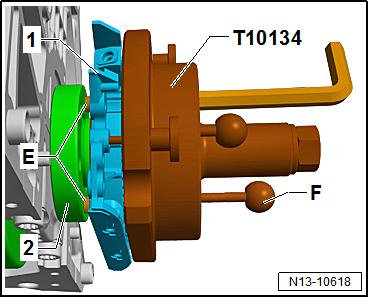
|
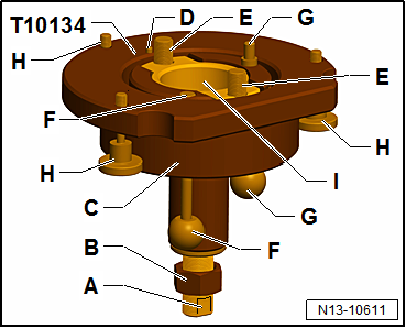
| Components of assembly tool -T10134-: |
| E - |
Hexagon socket head bolt (qty. 2) |
| F - |
Guide pin for petrol engines (red knob) |
| G - |
Guide pin for diesel engines (black knob) |
| H - |
Knurled screws (qty. 3) |
|
|
|
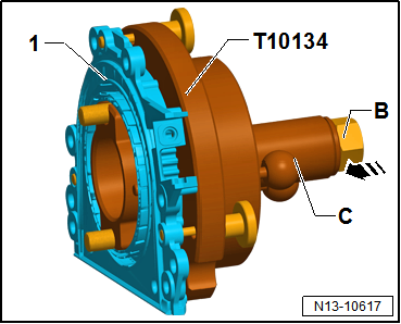
| Fitting sealing flange with sender wheel on assembly tool
-T10134-: |
| – |
Screw on nut -B- until just
before it touches the clamping surface -A-
of the threaded spindle. |
|
|
|
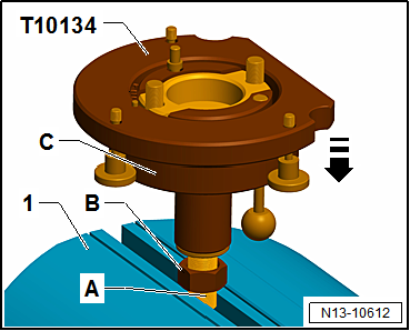
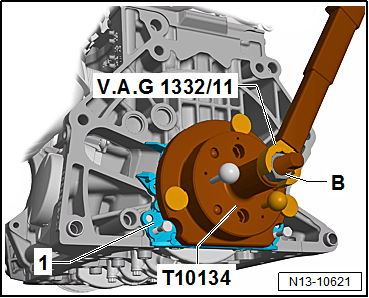
| – |
Clamp assembly device -T10134- at clamping surface
-A- of threaded spindle in a vice
-1-. |
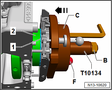
| – |
Press assembly housing -C-
downwards until it rests against nut -B-. |
| Inner part of assembly tool and assembly housing must be at
same height. |
|
|
|
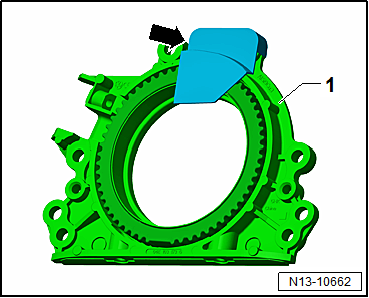
| – |
If fitted, remove securing clip
-arrow- from new sealing flange. |
Note
| Do not take the sender wheel out of the sealing flange or
rotate it out of position. |
|
|
|
| – |
Place sealing flange with front side facing down on a clean
level surface. |
| – |
Push sealing lip support ring -1-
downwards in -direction of arrow-
until it rests against level surface. |
|
|
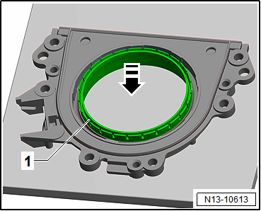
|
| Upper edge of sealing lip support ring
-1- and front edge of sealing flange
-2- must align
-arrows-. |
|
|
|
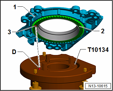
| – |
Place sealing flange -1- with
front side facing downwards onto assembly tool -T10134- so that
locating pin -D- is seated in hole
-3- in sender wheel hole
-2-. |
| The sealing flange must rest flat against the assembly tool. |
|
|
|
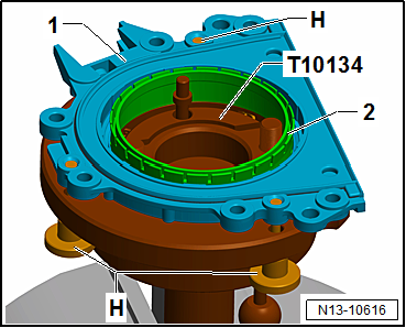
| – |
Screw knurled screws -H- into
sealing flange -1-. |
| – |
Press sealing flange -1- and
sealing lip support ring -2-
against surface of assembly tool -T10134- whilst tightening
knurled screws. |
| – |
This prevents locating pin from slipping out of sender wheel
hole. |
| – |
When installing sealing flange, ensure that sender wheel
remains fixed in assembly device. |
|
|
|
| Mounting assembly tool -T10134- with sealing flange
-1- on crankshaft flange: |
| The crankshaft flange must be free of grease and oil. |
| Engine is at “TDC” position
→ Anchor. |
| – |
Screw on nut -B- until it
reaches end of threaded spindle. |
| – |
Press threaded spindle of assembly tool -T10134- in
-direction of arrow-, until nut
-B- rests against assembly housing
-C-. |
| – |
Align flat side of assembly housing to sealing surface of
cylinder block on sump side. |
|
|
|
| – |
Attach assembly tool -T10134- together with sealing flange
-1- to crankshaft flange
-2-. |
| – |
To do this, screw hexagon socket head bolts
-E- into crankshaft flange (approx.
5 full turns) using a hexagon key. |
| – |
Push guide pin for petrol engines (red knob)
-F- into crankshaft flange. |
|
|
|
| – |
To guide sealing flange -1-,
screw two M6Ч35 mm bolts -2- into
cylinder block. |
|
|
|
| Bolting assembly tool -T10134- onto crankshaft flange: |
| – |
Push assembly housing -C- by
hand in -direction of arrow- until
sealing lip support ring -1- rests
against crankshaft flange -2-. |
| – |
Make sure that guide pin for petrol engines (red knob)
-F- is properly seated in hole in
crankshaft. This ensures that the sender wheel reaches its final
installation position. |
Note
| The guide pin for diesel engines (black knob) must not be
inserted in threaded hole of crankshaft. |
| – |
Tighten the two hexagon socket head bolts of assembly tool
hand-tight. |
| – |
Screw nut -B- by hand onto
threaded spindle until it rests against assembly housing
-C-. |
|
|
|
| Pressing sender wheel onto crankshaft flange using assembly
tool -T10134-: |
| – |
Tighten nut -B- of assembly
tool -T10134- to 35 Nm. |
| After the nut has been tightened to 35 Nm, a small air gap
must still be present between cylinder block and sealing flange
-1-. |
|
|
|
| Checking sender wheel installation position on crankshaft: |
| – |
Screw on nut -B- until it
reaches end of threaded spindle. |
| – |
Unscrew the two bolts -2- from
cylinder block. |
| – |
Pull guide pin for petrol engines (red knob)
-F- out of crankshaft flange. |
| – |
Unscrew knurled screws -H- from
sealing flange -1-. |
| – |
Unbolt assembly tool -T10134- from crankshaft flange,
unscrewing hexagon socket head bolts -E-
from crankshaft flange. |
| – |
Remove sealing lip support ring. |
|
|
|
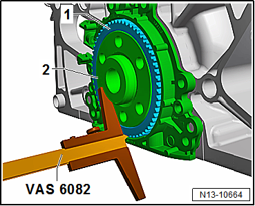
| – |
Position depth gauge -VAS 6082- on crankshaft flange
-2-. |
|
|
|
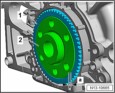
| – |
Measure distance -a- between
crankshaft flange -2- and sender
wheel -1-. |
| Specification: dimension -a- =
0.5 mm |
| – |
If specification is not achieved, press sender wheel further
in
→ Anchor. |
| – |
If specification is achieved, proceed with subsequent work
steps
→ Anchor. |
|
|
|
| Re-pressing sender wheel: |
| – |
Secure assembly tool -T10134- on crankshaft flange
-1-. |
| – |
Make sure that locating pin of assembly tool -T10134- is
properly seated in sender wheel hole. |
| – |
Tighten hexagon socket head bolts -E-
by hand. |
| – |
Push assembly tool -T10134- by hand against sealing flange
-1-. |
| – |
Screw nut -B- by hand onto
threaded spindle until it rests against assembly tool -T10134-. |
| – |
Push guide pin for petrol engines (red knob)
-F- into crankshaft flange. |
| – |
Screw knurled screws -H- into
sealing flange -1-. |
| – |
To guide sealing flange, screw two M6Ч35 mm bolts
-2- into cylinder block. |
|
|
|
| – |
Tighten nut -B- of assembly
tool -T10134- to 40 Nm. |
| – |
Check sender wheel installation position on the crankshaft
again
→ Anchor. |
| – |
If the specification is not achieved, tighten nut of
assembly tool -T10134- to 45 Nm. |
| – |
Check sender wheel installation position on the crankshaft
again
→ Anchor. |
| – |
Tighten bolts for sealing flange
→ Fig.. |
| – |
Install lower part of sump
→ Chapter „Removing and installing lower part of sump“. |
| – |
Install upper part of sump
→ Chapter „Removing and installing upper part of sump“. |
| – |
Install intermediate plate
→ Fig.. |
| – |
Install flywheel
→ Chapter. |
| → Fig. „“Sealing flange on gearbox side - specified torque and
tightening sequence”“ |
| → Fig. „“Plug for TDC drilling in cylinder block at rear –
specified torque”“ |
| → Chapter „Assembly overview - cylinder block, gearbox end“ |
| Engine speed sender -G28-
→ Chapter „Assembly overview - ignition system“ |
|
|
|
Special tools and workshop equipment
required
Counterhold -3067-
Removing
...
Other materials:
Fault in the function of the automatic gearbox
First read and observe the introductory information
and safety warnings Emergency programme
There is a fault in the system if all the displays on the instrument cluster
for the selector lever positions have a light background. The automatic gearbox
is running in an emergency programme. The ...
Vehicles with multilink suspension
The connecting pipe can be cut through at the cutting point
in order to renew the centre and rear silencers separately.
Cutting point is marked by an indentation on circumference
of exhaust pipe.
Special tools and ...
Removing and installing glove compartment
Special tools and workshop equipment
required
Torque wrench -V.A.G 1783-
Removing
–
Remove dash panel end cover on front passenger side
...
© 2016-2024 Copyright www.vwgolf.org

 Removing and installing flywheel
 Crankshaft