Volkswagen Golf Service & Repair Manual: Removing and installing output module for headlight -J667-/-J668-
 WARNING
| Risk of death due to high voltage! Risk of injury
and environmental pollution! |
| Observe operation and safety notes for gas discharge
bulbs
→ Chapter. |
| It is essential that the battery earth cable is
disconnected before any work on parts of the gas
discharge headlight is performed. The parts are marked
with a yellow high voltage symbol. |
|
 Note Note
| Output module for left headlight -J667- and output module
for right headlight -J668- are only fitted on gas discharge
headlights with cornering light. |
| Removal and installation are described for the left side.
Removal and installation on the right side are carried out in
the same way. |
| – |
Remove headlight
→ Chapter. |
|
|
|
| – |
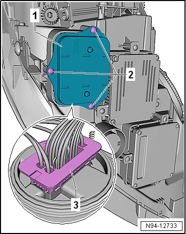
Pull output module for left headlight -J667--1-
off headlight. |
| – |
Press release button -4-. |
| – |
Disconnect electrical connector -3-. |
| Install in the reverse order of removal, observing the
following: |
 Caution
| Make sure seal is correctly seated when installing
the gas discharge bulb control unit. The ingress of
water will lead to permanent damage to the headlight. |
|
| – |
Check seal between control unit and headlight for damage. |
| → Chapter „Assembly overview - headlight“ |
|
|
|
WARNING
Risk of death due to high voltage! Risk of injury
and environmental pollution!
...
WARNING
Risk of death due to high voltage! Risk of injury
and environmental pollution!
...
Other materials:
Balancing wheel, balancing wheel with finish balancer
Before you start balancing the wheels, the following
requirements must be met.
Tyre pressure must be OK.
Tread must not be worn on one side. Tread depth should be at
least 4 mm.
T ...
Removing and installing front vehicle level senders -G78-/-G289-
Special tools and workshop equipment
required
Torque wrench -V.A.G 1410-
Removing
–
Disconnect co ...
Function
Fig. 127 In the stowage compartment on
the front passenger side: toll card reader
First read and observe the introductory information
and safety warnings Using the toll card system
Switch on the navigation system and insert a suitable ETC card in the toll card
reader (arrow).
The de ...
© 2016-2024 Copyright www.vwgolf.org

 Removing and installing gas discharge bulb control unit -J343-/-J344-
 Removing and installing control unit for daytime running light and side
light -J860-/-J861-
Removing and installing control unit for daytime running light and side
light -J860-/-J861-