Volkswagen Golf Service & Repair Manual: Removing and installing control unit 1 for information electronics -J794-
| Special tools and workshop equipment
required |
|
|
|
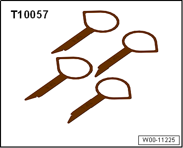
| Radio release tool -T10057- |
|
|
|
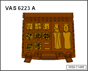
| Protective cap for wiring harness connector -VAS 6223/9- |
| If the control unit is replaced, select the
Replace function of the respective
control unit in Guided fault finding
→ Vehicle diagnostic tester. |
| – |
Switch off ignition and all electrical consumers, and remove
ignition key. |
| – |
Open glove compartment. |
| – |
Eject any data medium that is still in control unit 1 for
information electronics -J794-. |
|
|
|
| – |
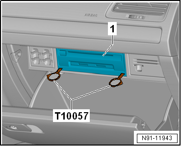
Insert 2 radio release tools -T10057- into slots in control
unit 1 for information electronics -J794--1-
until they engage. |
| The pointed projections on the grip rings point outwards. |
| – |
Grasp hold of grips on radio release tool -T10057- and pull
control unit 1 for information electronics -J794--1-
out of dash panel. |
| – |
Release and unplug connectors at control unit 1 for
information electronics -J794--1-. |
| Version with digital sound package control unit -J525- |
|
|
|
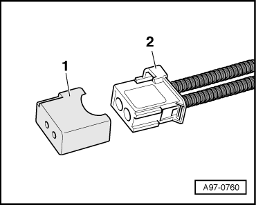
| – |
Push protective cap for cable connector -VAS 6223/9--1-
onto connector of MOST bus -2-. |
| – |
Press locking lugs on control unit 1 for information
electronics -J794- and pull out radio release tool -T10057-. |
| Install in the reverse order of removal. When doing this,
note the following: |
| – |
Slide control unit 1 for information electronics -J794- into
glove box until it engages. |
|
|
|
Special tools and workshop equipment
required
Removal wedge -3409-
...
Other materials:
Dimensions – lettering on wing
Note
The dimensions shown here for “GTI” as an example are valid for all
emblems.
1 -
Emblem
Variations in appearance possible depending on the (special) model.
2 -
Height dimension
5.0 ± 1 mm, fr ...
Function and operation
Fig. 180 In the lower section of the centre
console: Driving Mode Selection button
First read and observe the introductory information
and safety warnings The driver can choose from up to 5 different driving
modes with a variety of characteristics:
Driving m ...
Battery
Battery - general notes
Note
All instructions and notes regarding this chapter are
available under
→ Electrical System, General Information; Rep. gr.27.
...
© 2016-2024 Copyright www.vwgolf.org

 Removing and installing infotainment system display
 Sound system