Volkswagen Golf Service & Repair Manual: Removing and installing clutch engagement
| Dual clutch removed
→ Chapter. |
| – |
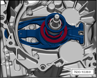
Remove large engaging lever with small engagement bearing. |
 Note Note
| The upper section of bushing cannot be removed or installed
alone. It is always removed or installed together with lower
section of guide sleeve and »small«
engaging lever. |
|
|
|
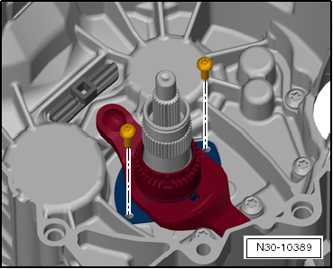
| – |
Undo and remove bolts and remove
»small« engagement lever together with upper and lower
section of guide sleeve. |
|
|
|
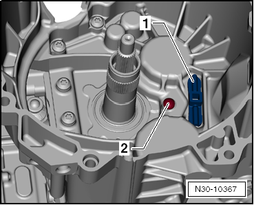
| Hinge mounting -1- and ball pin
-2- have been installed. |
| Only replace the ball pin -2-
when it is worn
→ Anchor. |
| Observe the following when installing a new engaging lever
»K 2«: |
|
|
|
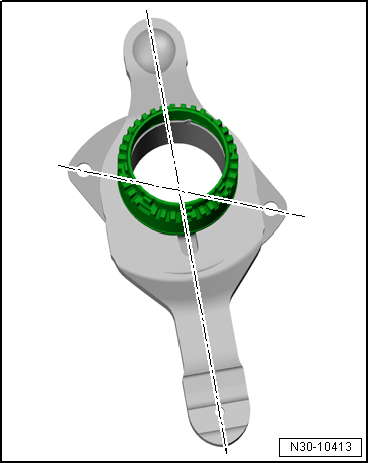
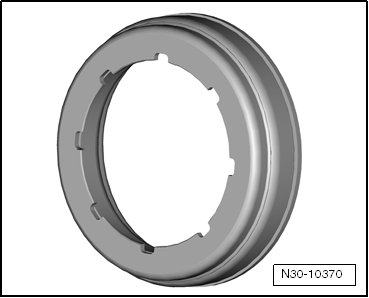
| The new engaging lever »K2« with
upper and lower section of guide sleeve will be delivered in
transport position -illustration-
and must be set to installation position prior to installation. |
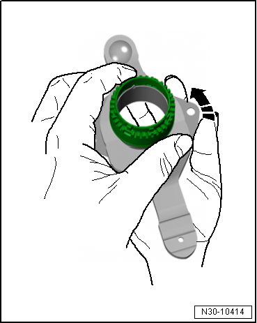
| Setting engaging lever »K2« to
installation position: |
|
|
|
| – |
Hold upper section of guide sleeve with one hand. With the
other hand turn the lower section of guide sleeve in direction
of arrow until the sleeve moves freely. |
Note
| Apply high force to hold both sections, as this is necessary
for turning the lower section of the guide sleeve. |
|
|
|
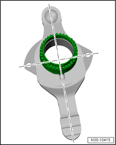
| If the engaging lever is in installation position, the holes
of the lower section of guide sleeve are at right angles to the
engaging lever. The sleeve moves freely. |
| – |
When installing a new engaging lever, the position of the
engaging bearings “K 1” and “K 2” must be adjusted
→ Chapter. |
|
|
|
| – |
Install »small« engagement lever
together with upper and lower section of bushing. Insert and
tighten new bolts. |
| Specified torques:
→ Item |
|
|
|
| – |
Insert »large« engaging lever
with measured shims for “K 1” and “K 2” and with small
engagement bearing. |
| The large shim is inserted into the large engagement
bearing, with the hemispherical side of the shim facing
downwards. |
| The small shim goes under the small engagement bearing.
Therefore, insert shim first. |
|
|
|
| The shim and the small engagement bearing only fit in one
position due to the 8 grooves. |
| – |
By turning, check that parts have been installed correctly
and that grooves are seated correctly. |
| – |
Check both engaging levers are seated correctly. |
| – |
Install dual clutch
→ Chapter. |
|
|
|
1 -
Shim for “K 1”
Determining thickness
→ Chapter.
2 -
Large engaging lever for “K 1”
Wi ...
The position of the engagement bearings “K 1” and “K 2” must
only be adjusted after the following work:
Clutch has been renew ...
Other materials:
Acoustic and optical ParkPilot signals
Fig. 150 ParkPilot display of the area
around the vehicle (colour)
Fig. 151 Mini ParkPilot display of the
area around the vehicle (colour)
First read and observe the introductory information
and safety warnings
Key
and
Meaning
...
Assembly overview - side trim panel
Note
The illustration shows the side trim panel on the left side. The
right-hand side is similar (mirror image of left-hand side).
1 -
Side trim panel
Removing and installing
→ Chapter
2 -
Clip
...
Assembly overview - glove compartment
1 -
Glove compartment
Removing and installing
→ Chapter
2 -
Damper element
For glove compartment lid
With glove compartment light switch -E26-
Removing and installing
→ Chapter
3 -&nbs ...
© 2016-2024 Copyright www.vwgolf.org

 WARNING
 Assembly overview - clutch engagement
 Adjusting clutch engagement