Volkswagen Golf Service & Repair Manual: Removing and installing anti-roll bar
| Special tools and workshop equipment
required |
|
|
|
| Torque wrench -V.A.G 1332- |
|
|
|
| Engine and gearbox jack -V.A.G 1383 A- |
| – |
If fitted, remove lower noise insulation
→ General body repairs, exterior; Rep. gr.66. |
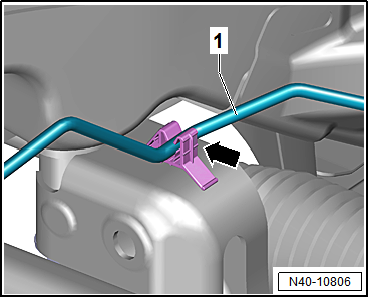
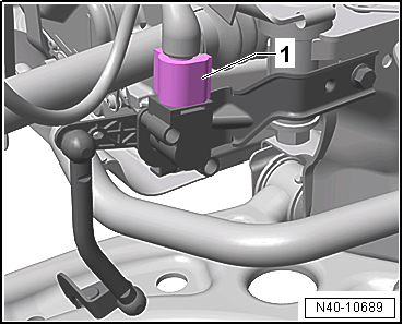
| Vehicles with natural gas engines |
|
|
|
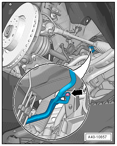
| – |
Unclip natural gas line -1-
from clip -arrow-. |
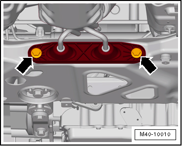
| Vehicles with exhaust system |
|
|
|
| – |
Detach exhaust system bracket from subframe
-arrows-. |
| Continuation for all vehicles |
|
|
|
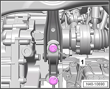
| – |
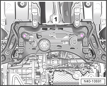
Unscrew bolts -1- for pendulum
support. |
|
|
|
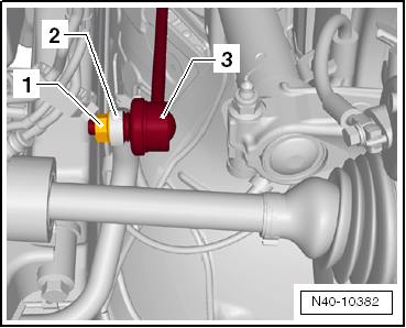
| – |
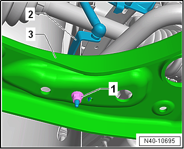
Unscrew nut -1- from coupling
rod -3- on both sides. |
| – |
Pull out coupling rod -3- from
anti-roll bar -2- on left and right
side. |
|
|
|
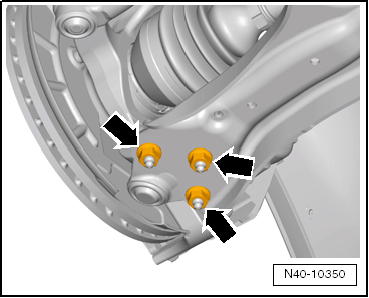
| – |
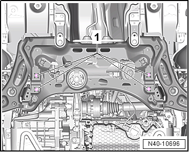
Remove nuts -arrows- on left
and right sides of vehicle. |
|
|
|
| Vehicles with vehicle level sender |
| – |
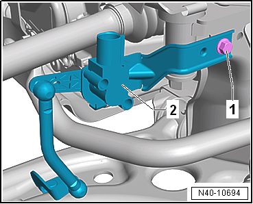
Disconnect connector -1- on
front left vehicle level sender -G78- and/or front right vehicle
level sender -G289-, as applicable. |
|
|
|
| – |
Pull bracket -2- for front left
vehicle level sender -G78- and/or for front right vehicle level
sender -G289- out of suspension link -3-,
as applicable |
|
|
|
| – |
Remove front left vehicle level sender -G78--2-
and/or front right vehicle level sender -G289-, as applicable. |
| Continuation for all vehicles |
|
|
|
| – |
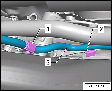
Pull wiring harness -3- clips
-1- and -2-
off subframe and steering rack. |
|
|
|
| – |
Unscrew bolts -1- for anti-roll
bar. |
|
|
|
| – |
Unscrew bolts -1- for steering
rack. |
| – |
Prise steering rack out of dowel sleeves of subframe. |
|
|
|
| – |
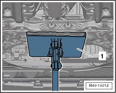
Position engine and gearbox jack -V.A.G 1383 A--1-
under subframe |
| – |
Fixing subframe
→ Chapter and lowering approx. 10 cm. |
|
|
|
| – |
Pull out spreader clip -arrow-. |
| – |
Lower subframe using engine and gearbox jack -V.A.G 1383 A-
until anti-roll bar can be removed to rear. |
| Install in reverse order of removal, observing the
following: |
 Note Note
| Lever on vehicle level sender must face towards outside of
vehicle. |
| Thread of vehicle level sender must be screwed into outer
hole in suspension link. Retaining lug for vehicle level sender
must engage in inner hole in order to guarantee correct
installation position. |
| – |
On vehicles with vehicle level sender, carry out basic
settings for wheel damper electronics → Vehicle
diagnostic tester. |
| → Chapter „Assembly overview - subframe“ |
| → Chapter „Assembly overview - steering column“ |
| → Chapter „Assembly overview - front vehicle level senders“ |
| Bolts for pendulum support, except for e-Golf
→ Rep. gr.10 |
| Bolts for pendulum support, e-Golf
→ Electrical system; Rep. gr.93 |
| Bolts for noise insulation
→ General body repairs, exterior; Rep. gr.66. |
| Exhaust pipes double clamp
→ Rep. gr.26. |
| → Chapter „Torque settings for wheel bolts“ |
| If a crooked steering wheel is determined during the road
test even though locating pins -T10486/1- were used, check wheel
alignment. In this case the wheel alignment test results must be
archived in the vehicle files. |
|
|
|
Special tools and workshop equipment required
Assembly tool -T10205-
Torque wrench -V.A.G 1332-
Hydraulic press -VAS 6178-
...
Special tools and workshop equipment
required
Torque wrench -V.A.G 1332-
Removin ...
Other materials:
Overview of fitting locations – central locking
1 -
Coupling station
Fitting location: right A-pillar
To separate connections, release bellows at pillar
2 -
Onboard supply control unit -J519-
Location: Under dash panel on driver side
Removing
→ Electrical syste ...
Luggage compartment cover
Fig. 96 In the luggage compartment: removing
and installing the luggage compartment cover
First read and observe the introductory information
and safety warnings When attached, the supporting straps will automatically
raise or lower the luggage compartment cover when you open or close the ...
Setting the gloss level of HS clear coats and HS top coats
Issued 04.2013
The gloss level of HS clear coats and HS top coats is set by
mixing them with matting additive -LVM 769 810 A2- for plastic
and metal substrates.
The information on the factors that influence gloss level
...
© 2016-2024 Copyright www.vwgolf.org

 Repairing subframe
 Removing and installing coupling rod