Volkswagen Golf Service & Repair Manual: Detecting leaks in refrigerant circuit using leak detecting system -VAS
6196- or leak detecting system -VAS 6201- or a later model
 Note Note
| Small leaks can be detected with, for example, an UV leak
detector additive. |
| – |
Evacuate refrigerant circuit using an air conditioner
service station
→ Chapter. |
Note
| If a larger leak is detected during the evacuation process,
determine cause and rectify as described
→ Chapter. |
| If during the evacuation process no leak is detected or a
very small leak is detected that but cannot be located, proceed
as follows
→ Chapter. |
| Refrigerant gas is quickly dispersed by air motion.
Therefore drafts must be avoided during a search for leaks. |
| If the refrigerant circuit is completely empty, charge with
about 10% of refrigerant capacity (sticker R134a or
vehicle-specific workshop manual). |
|
|
|
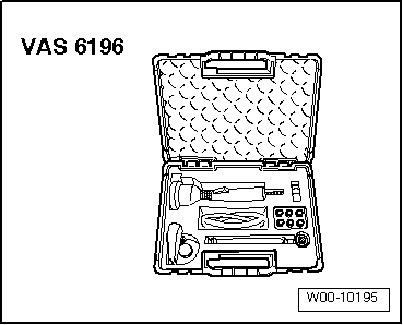
| Leak detecting system -VAS 6196- |
|
|
|
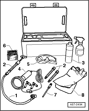
| Leak detecting system -VAS 6201- or later model |
| 1 - |
Hand pump with low-pressure service hose, service coupling
and non-return valve -VAS 6201/1- |
| 2 - |
Cartridge -VAS 6201/2- |
| 3 - |
Cleaning solution -VAS 6201/3- |
| 4 - |
UV leakage detector lamp -VAS 6201/4- |
| 5 - |
UV absorbing eye protection -VAS 6201/6- |
| 8 - |
Protective gloves -VAS 6201/9- |
|
|
|
| Injecting leak detecting additive to an empty refrigerant
circuit |
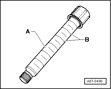
| The cartridge -A- contains
15.4 ml of leak detecting additive (one unit
-B- equates to 2.5 ml). |
|
|
|
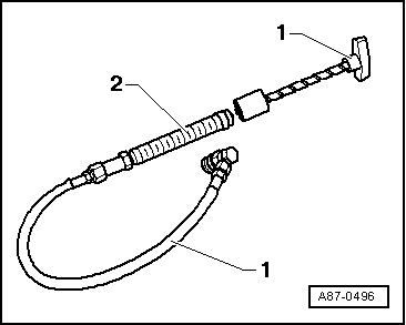
| – |
Assemble hand pump -VAS 6201- item -1-
and cartridge item -2--VAS 6201/2-. |
| – |
Connect filler hose -VAS 6201/8- (
→ Anchor item -7-) to
hand pump. |
| – |
Open service valve of hand pump. |
|
|
|
| The leak detecting additive can be injected into the empty
refrigerant circuit via an open circuit connection. |
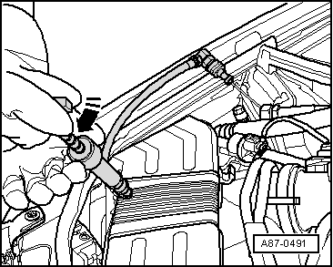
| – |
Open an easily assessable connection in the refrigerant
circuit. |
| – |
Cover area of connection with foil or absorbent paper. |
| – |
Turn T-bar of hand pump until the leak detecting additive
flows out of the tube. |
| – |
Inject 2.5 ± 0.5 ml (millilitre = cm3)
of leak detecting additive into the refrigerant circuit. |
Note
| Note the following, if a leak detecting additive has been
injected during a previous repair of the refrigerant circuit,
only inject new leak detecting additive if the refrigerant
machine oil has been replaced. If only some of the refrigerant
machine oil was replaced then only the respective amount of leak
detecting additive should be injected. If for example 100 ml of
machine oil was replaced on a vehicle with 250 ml of refrigerant
machine oil, inject only 1 ml (cm3)
of leak detecting additive. |
| – |
Renew O-rings at opened connection. |
| – |
Reassemble refrigerant circuit again. |
| – |
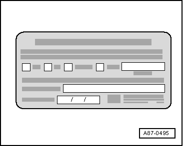
Attach a label, close to the service connection, which has
information showing that the refrigerant circuit has been
injected with a leak detecting additive. |
| – |
Evacuate and fill the refrigerant circuit as per
specifications
→ Chapter and
→ Chapter. |
| – |
Start air conditioning system. |
Note
| The air conditioning system must be operated for at least
60 minutes to ensure that the injected leak detecting additive
is distributed throughout the entire refrigerant circuit (air
conditioner compressor must run). The leak may become visible
after a short period, but this depends on the size of the leak. |
| – |
Use UV lamp VAS 6196/4 to search for the leak in the
refrigerant circuit
→ Anchor. |
Note
| Using cleaning solution -VAS 6201/3-, clean the engine
compartment and, if necessary, the components of the refrigerant
circuit, to remove leak detection additive residue left from the
repair work. |
| Injecting leak detecting additive to a charged refrigerant
circuit |
Note
| Note the following, if a leak detecting additive has been
injected during a previous repair of the refrigerant circuit,
only inject new leak detecting additive if the refrigerant
machine oil has been replaced. If only some of the refrigerant
machine oil was replaced then only the respective amount of leak
detecting additive should be injected. If for example 100 ml of
machine oil was replaced on a vehicle with 250 ml of refrigerant
machine oil, inject only 1 ml (cm3)
of leak detecting additive.
|
| A small amount of leak detecting additive remains in the
service connection. Carefully remove the remains as this will
help to prevent these remains being falsely identified as a leak
when leak detection is carried out in the future. |
|
|
|
| The cartridge -A- contains
15.4 ml of leak detecting additive (one unit
-B- equates to 2.5 ml). |
|
|
|
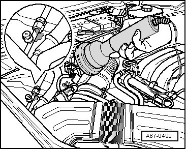
| – |
Remove sealing cap from service connection on low-pressure
side of refrigerant circuit. |
| – |
Assemble hand pump -VAS 6201- item -1-
and cartridge item -2--VAS 6201/2-. |
Note
| Ensure the hose of the hand pump is completely filled with
leak detecting additive. |
| – |
Fit the quick release coupling to the service connection of
the low-pressure side and open the service coupling by turning
the hand wheel. Hold hose upwards and turn T-bar of hand pump
until the leak detecting additive starts to flow out of the
tube. |
|
|
|
| – |
Cover area of service connection on vehicle with foil or
absorbent paper. |
| – |
Turn T-bar of hand pump and inject 2.5 ± 0.5 ml (millilitre
= cm3) of leak detecting additive
into the refrigerant circuit. |
|
|
|
| – |
Close the service coupling and remove it from the service
connection. |
| – |
Remove the remains of the leak detecting additive from the
service connection, with for example, absorbent paper. |
| – |
Seal service connection using sealing cap. |
| – |
If necessary, clean the area of the service connection using
the cleaning solution. |
| – |
Attach a label, close to the service connection, which has
information showing that the refrigerant circuit has been
injected with a leak detecting additive. |
| – |
Start air conditioning system. |
Note
| The air conditioning system must be operated for at least
60 minutes to ensure that the injected leak detecting additive
is distributed throughout the entire refrigerant circuit (air
conditioner compressor must run). The leak may become visible
after a short period, but this depends on the size of the leak. |
| – |
Use UV lamp VAS 6196/4 to search for the leak in the
refrigerant circuit
→ Anchor. |
Note
| Using cleaning solution -VAS 6201/3-, clean the engine
compartment and, if necessary, the components of the refrigerant
circuit, to remove leak detection additive residue left from the
repair work. |
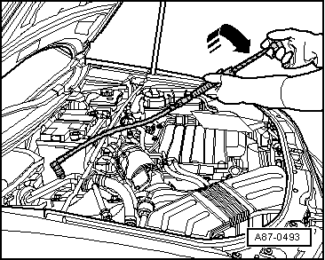
| Searching for leaks in the refrigerant circuit using UV lamp
VAS 6196/4 |
 WARNING
| Do not look into the UV lamp. |
| Do not point the UV lamp at another person. |
|
Note
| The air conditioning system must be operated for at least
60 minutes to ensure that the injected leak detecting additive
is distributed throughout the entire refrigerant circuit (air
conditioner compressor must run). The leak may become visible
after a short period, but this depends on the size of the leak. |
| For leaks on the evaporator, the additive can wash off with
the condensed water and leak out from the condensed water
drain-off. As the evaporator is not accessible on the majority
of models without a great amount of pre-preparation, a check of
the condensed water drain point can indicate a leaking
evaporator. The additive must have been in the refrigerant
circuit for a long time to make this possible. |
| The eye protect is not only required to protect the eyes, it
also amplifies the illumination of the additive under the UV
lamp. |
| Independent of the accessibility to the various components
of the refrigerant circuit, it may become necessary to remove
certain components from the vehicle (e.g. bumper or air filter). |
|
|
|
| – |
Position the vehicle in a darker area of the workshop (in
daylight or under strong lighting the effect of the UV lamp is
greatly reduced). |
| – |
Check the accessibility to the various components of the
refrigerant circuit and remove components in the vicinity of the
refrigerant circuit that obstruct the view of the respective
circuit components (e.g. sound insulation and bumper). |
| – |
Protect eyes with protective glasses. |
| – |
Connect UV lamp to a 12 V battery (vehicle battery). Ensure
that it is connected to the correct terminals. |
| – |
Switch on UV lamp and illuminate components of the
refrigerant circuit. Locations where leaking refrigerant along
with refrigerant oil and leak detecting additive can leak out,
light-up (fluorinate) under UV light. |
Note
| The leak detection additive can be allowed to remain in the
refrigerant circuit. |
| Using cleaning solution -VAS 6201/3-, clean the engine
compartment and, if necessary, the components of the refrigerant
circuit, to remove leak detection additive residue left from the
repair work. |
|
|
 |
Note
Small leaks can be detected with, for example, an electronic
leak detector.
–
Evacuate refrigerant circuit using an ...
© 2016-2024 Copyright www.vwgolf.org

 Searching for leaks in refrigerant circuits using leak detector -V.A.G 1796