Volkswagen Golf Service & Repair Manual: Checking fuel pressure sender -G247-
| Special tools and workshop equipment
required |
| Vehicle diagnostic tester |
|
|
|
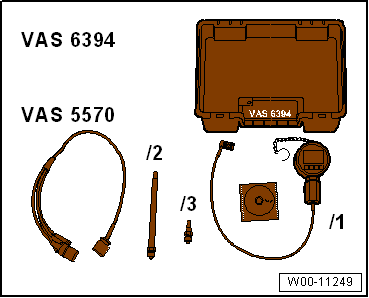
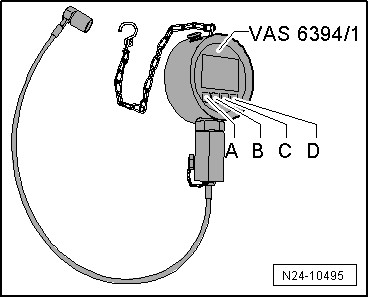
| Pressure sensor tester -VAS 6394- |
| Test instrument adapter/DSO (3-pin) -VAS 5570- |
| Socket, 27 mm (commercially available) |
The fuel system is under high pressure.Risk of injury due to fuel which
may spurt out.Release high pressure.
| Risk of functional impairment due to soiling
→ Chapter. |
| – |
Remove fuel pressure sender - G247-
→ Chapter. |
|
|
|
| – |
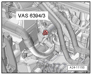
Lubricate taper seal of adapter -VAS 6394/3- with clean
engine oil and screw into fuel rail (22 Nm). |
|
|
|
| – |
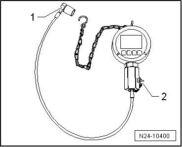
Unscrew plug -2- and screw fuel
pressure sender - G247- into tester -VAS 6394/1-. |
| – |
Connect pressure line -1- of
tester to adapter -VAS 6394/3-. |
|
|
|
| – |
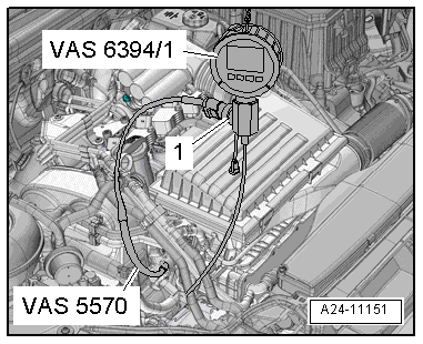
Connect vehicle and fuel pressure sender - G247-
electrically using test instrument adapter/DSO (3-pin) -VAS
5570-. |
|
|
|
| – |
Switch on tester -VAS 6394/1- by pressing button
-A- once briefly. |
 Note Note
| When button -A- is pressed for
2 seconds, the illumination is switched on for 20 seconds. |
| If tester -VAS 6394/1- does not indicate 0 bar, zero the
tester
→ Operating instructions. |
| – |
Connect vehicle diagnostic tester. |
| – |
Start engine and run at idling speed. |
| – |
Select “Engine electronics” in the self-diagnosis program. |
| – |
Then, select “Measured values”. |
| – |
Select “Fuel pressure” from the list. |
| – |
Compare pressure displayed on tester -VAS 6394/1- with
actual value displayed on vehicle diagnostic tester. |
| – |
Watch the fuel pressure on the vehicle diagnostic tester. |
| A maximum pressure deviation of 5 bar is permissible. |
| – |
If the deviation is greater than 5 bar, renew fuel pressure
sender - G247-. |
| – |
Repeat test with new fuel pressure sender - G247- and
compare both measured values. |
| – |
If measured values are now the same, install new fuel
pressure sender - G247-. |
| – |
If measured values are not the same again, check electrical
connection between fuel pressure sender - G247- and engine
control unit -J623-
→ Current flow diagrams, Electrical fault finding and Fitting
locations. |
| → Chapter „Assembly overview - fuel rail with injectors“ |
|
|
|
Special tools and workshop equipment
required
Assembly tool -T10118-
...
Other materials:
Principle circuit diagrams for various purging circuits
Note
The arrows in the following illustrations show the direction
of flow of the refrigerant during purging. The refrigerant flows
against the direction of flow during normal conditioning of the
air, which is why the high-pressure system o ...
Drawers
Fig. 116 Drawer under the front seat
First read and observe the introductory information
and safety warnings A drawer may be located under each of the front seats
.
Opening or closing the drawer
To open, press the button in the drawer grip and open the drawer.
To close, push the dra ...
Assembly overview - suspension, multi-link suspension, front-wheel drive
1 -
Wheel bearing housing
Removing and installing
→ Chapter
2 -
Bonded rubber bush
Renewing
→ Chapter.
3 -
Bolt
Specified torque
͛ ...
© 2016-2024 Copyright www.vwgolf.org

 Removing and installing fuel pressure sender -G247-