Volkswagen Golf Service & Repair Manual: Assembly overview – heater unit
 Note Note
| There are different designs and makes of heater. The
individual components of the various heaters are similar but not
identical. The combined fitting of different makes of component
is therefore not permissible
→ Electronic Parts Catalogue. |
| The following illustrations show a “Valeo” heater unit. For
information on distinguishing features with respect to other
makes refer to
→ Chapter. |
| The figures show a left-hand drive vehicle. The procedure is
analogous. |
|
|
|
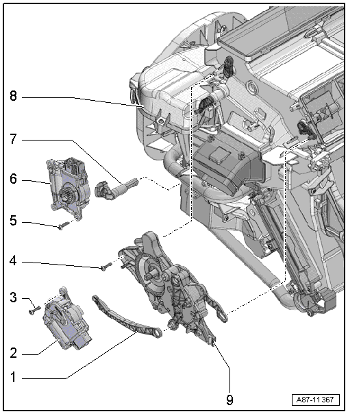
| For actuation of defroster and air distributor flap |
| 2 - |
Air distribution flap control motor -V428- |
| With potentiometer for air distribution flap control motor -G645-. |
| Checking: Use vehicle diagnostic tester in “Guided fault finding”
mode and → Current flow
diagrams, Electrical fault finding and Fitting locations |
| Removing and installing
→ Chapter |
| 6 - |
Temperature flap control motor -V68- |
| With potentiometer for temperature flap control motor -G92-. |
| Checking: Use vehicle diagnostic tester in “Guided fault finding”
mode and → Current flow
diagrams, Electrical fault finding and Fitting locations |
| Removing and installing
→ Chapter |
| For actuation of heated air flap. |
| Different versions
→ Chapter. |
| The combined fitting of different makes of component is not
permissible. |
| The following illustrations show the heater unit from “Valeo”. |
| The design is largely identical to that of the heater and air
conditioning unit. |
| Following components are not fitted: expansion valve, condensation
drain, evaporator etc. |
| Instead of the evaporator a flow rate limiter is fitted (only on
vehicles without air conditioning system). |
| There is no opening for the expansion valve in the plenum chamber
back wall seal or this is closed off by a foam pad |
| Removing and installing
→ Chapter |
| 9 - |
Defroster and air distribution flap actuation unit |
| Removing and installing
→ Chapter |
| Heater, heat exchanger, auxiliary air heater element |
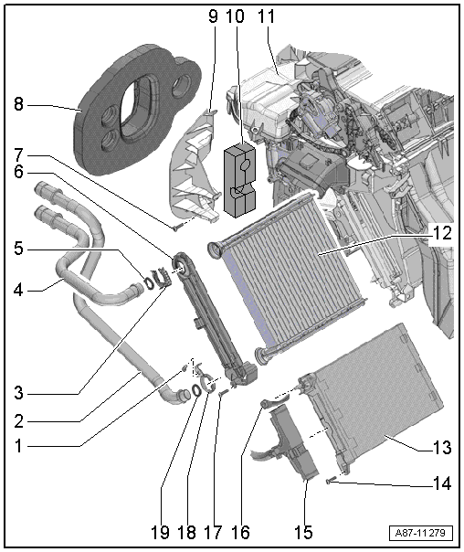
| 2 - |
Coolant pipe with heat exchanger |
| Different versions. Refer to
→ Electronic Parts Catalogue. |
| Coolant supply from the engine |
| Removing and installing
→ Chapter |
| 4 - |
Coolant pipe with heat exchanger |
| Different versions. Refer to
→ Electronic Parts Catalogue. |
| Coolant return to the engine |
| Removing and installing
→ Chapter |
| Different versions. Refer to
→ Electronic Parts Catalogue. |
| For sealing and insulation. |
| No opening for expansion valve on vehicles with no air conditioning
system
→ Electronic Parts Catalogue. |
| On vehicles without auxiliary air heater element -Z35- with
auxiliary air heater control unit -J604- the opening for the auxiliary
heater is closed. |
| Removing and installing
→ Chapter |
| Different versions. Refer to
→ Electronic Parts Catalogue. |
| Removing and installing
→ Chapter |
| 13 - |
Auxiliary air heater element -Z35- with auxiliary air heater control
unit -J604- |
| Removing and installing
→ Chapter |
| For auxiliary air heater element -Z35- with auxiliary air heater
control unit -J604-. |
| 16 - |
Earth cable for auxiliary air heater element -Z35- with auxiliary
air heater control unit -J604-. |
| Different versions. Refer to
→ Electronic Parts Catalogue. |
| Air intake housing, dust and pollen filter, fresh air blower, flap
control |
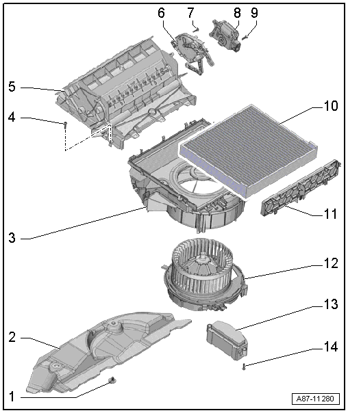
| 1 - |
Plastic bolt or plug depending on version |
| Removing and installing
→ Chapter |
| 3 - |
Housing for fresh air blower and dust and pollen filter |
| With fresh air and air recirculation flap |
| Different versions. Refer to
→ Electronic Parts Catalogue. |
| Removing and installing
→ Chapter |
| Only on vehicles with Climatronic. |
| Only on vehicles with Climatronic. |
| 8 - |
Air recirculation flap control motor -V113- |
| Without potentiometer with limit switches at end stops
→ Current flow
diagrams, Electrical fault finding and Fitting locations. |
| Checking: Use vehicle diagnostic tester in “Guided fault finding”
mode and → Current flow
diagrams, Electrical fault finding and Fitting locations |
| Removing and installing
→ Chapter. |
| 10 - |
Dust and pollen filter |
| Different versions. Refer to
→ Electronic Parts Catalogue. |
| Change interval:
→ Maintenance tables. |
| Removing and installing
→ Chapter. |
| For dust and pollen filter. |
| 12 - |
Fresh air blower -V2- |
| Checking: Use vehicle diagnostic tester in “Guided fault finding”
mode and → Current flow
diagrams, Electrical fault finding and Fitting locations |
| Removing and installing
→ Chapter |
| 13 - |
Fresh air blower control unit -J126- |
| Checking: Use vehicle diagnostic tester in “Guided fault finding”
mode and → Current flow
diagrams, Electrical fault finding and Fitting locations |
| Removing and installing
→ Chapter. |
Removing and installing fresh air blower -V2-
| Removal and installation are identical with procedure for
vehicles with air conditioning system
→ Chapter. |
|
|
|
| Removing and installing fresh air blower
control unit -J126- |
| Removal and installation are identical with procedure for
vehicles with air conditioning system
→ Chapter. |
|
| Removing and installing dust and pollen
filter |
| Removal and installation are identical with procedure for
vehicles with air conditioning system
→ Chapter. |
|
|
|
| Removing and installing heater unit |
| It is not necessary to extract the refrigerant and to remove
the expansion valve. Further removal and installation are
identical with procedure for vehicles with air conditioning
system
→ Chapter. |
|
|
|
It is not necessary to extract the refrigerant and to remove
or disassemble the expansion valve and the evaporator. Further
procedure is identical with procedure for vehicles wi ...
Other materials:
2-pack HS wet-on-wet surfacer
Designation:
2-pack HS wet-on-wet surfacer -LVM 013 008 A4-, light grey
2-pack HS wet-on-wet surfacer -LVM 013 905 A4-, black
Issue 03.2015
Product description
...
Adjusting rear lid
Special tools and workshop equipment
required
Torque wrench -V.A.G 1331-
Setting gauge -3371-
Note
Vehicle must be ...
Assembly overview - bench seat / individual seats
1 -
Rear bench seat
Allocation
→ Electronic Parts Catalogue
Removing and installing
→ Chapter
2 -
Guide
For ISOFIX child seat anchor
Qty. 4
Removing and installing
→ Chapter
...
© 2016-2024 Copyright www.vwgolf.org

 Heater unit
 Dismantling and assembling heater unit