Volkswagen Golf Service & Repair Manual: Assembly overview - drive unit of air conditioner compressor, Golf GTE
| 1 - |
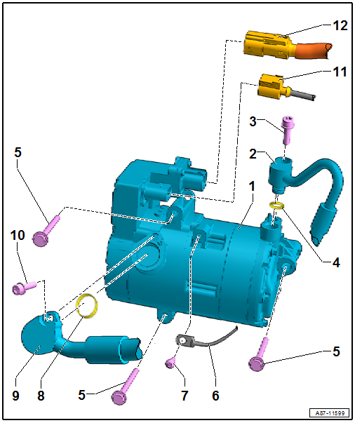
Electrical air conditioner compressor -V470- |
| With control unit for air conditioner compressor -J842- and
electrical air conditioner compressor -V470- |
| → Chapter „Removing air conditioner compressor from and installing to
bracket“ |
| Removing and installing
→ Chapter „Removing and installing air conditioner compressor“ |
 Note
Note
| The bolting points of the air conditioner compressor and the engine
bracket must be checked prior to installation. The contact surfaces must
be clean, rust- and grease-free. Otherwise, repair contact surfaces
using contact surface cleaning set -VAS 6410-
→ Electrical system; General information; Rep. gr.97. |
| The electrical air conditioner compressor -V470- is supplied with
power via a fuse installed in the power and control electronics for
electric drive -JX1-. |
| 2 - |
Refrigerant line, high-pressure side |
| Renewing
→ Chapter; for versions, refer to
→ Electronic Parts Catalogue |
| Moisten lightly with refrigerant oil before installing |
| Different versions. Refer to
→ Electronic Parts Catalogue. |
Note
| If the air conditioner compressor is secured with aluminium bolts
(for different versions refer to
→ Electronic Parts Catalogue), use the aluminium bolts only
once, i.e. renew them. Specified torque for aluminium bolts 8 Nm + 180° |
| Check contact surface before bolting it on, and clean it as
necessary. |
Note
| The contact surfaces must be clean, rust- and grease-free.
Otherwise, repair contact surfaces using contact surface cleaning set
-VAS 6410-
→ Electrical system; General information; Rep. gr.97. |
| Renewing
→ Chapter; for versions, refer to
→ Electronic Parts Catalogue |
| Moisten lightly with refrigerant oil before installing |
| 9 - |
Refrigerant line, low-pressure side |
| With control wire from operating unit, Climatronic control unit
-J255-
→ Current flow diagrams, Electrical fault finding and Fitting locations |
| 12 - |
High-voltage cable to power and control electronics for electric
drive -JX1- (with control unit for high-voltage battery charging unit
-J1050-) |
Note
The illustration shows a different version.
1 -
Poly V-belt
Removing and ...
1 -
Bolt
Qty. 3.
4.5 Nm
2 -
Sealing cap
3 -
Nut
25 Nm
...
Other materials:
Conicity
Conicity is caused by a slight offset of the tread and/or
the belt (amounting to a few tenths of a millimetre) relative to
the geometric centre of the tyre. Taper is not visible and
cannot be measured with equipment available in the workshop.
& ...
Removing and installing Bowden cable
Removing
–
Open bonnet.
–
Remove release lever
→ Chapter.
–
Remove Bowden cable -3- from mounting
bracket -5--arrow a-.
– ...
Adjusting the
head restraints
Fig. 46 Adjusting front head restraint
Fig. 47 Adjusting rear head restraint
First read and observe the introductory information
and safety warnings Every seat is fitted with a head restraint. The centre
rear head restraint is designed solely for use with the centre rear seat. This head ...
© 2016-2024 Copyright www.vwgolf.org

 Assembly overview - drive unit of air conditioner compressor, Golf and Golf
Estate
Assembly overview - drive unit of air conditioner compressor, Golf and Golf
Estate Assembly overview - belt pulley, Denso air conditioner compressor