Volkswagen Golf Service & Repair Manual: Assembly overview - control unit and hydraulic unit, RHD vehicles
| 1 - |
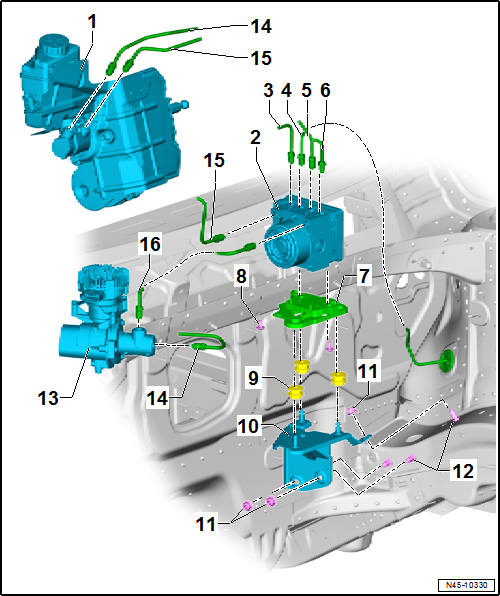
Brake servo and brake master cylinder |
| Assembly overview
→ Chapter. |
| Checking brake servo → Vehicle
diagnostic tester |
| Removing and installing
→ Chapter |
| Removing and installing brake master cylinder
→ Chapter. |
| 2 - |
ABS hydraulic unit -N55- with ABS control unit -J104- |
| Fitting location overview
→ Chapter |
| Assembly overview
→ Chapter. |
| Removing and installing
→ Chapter |
| Separating ABS control unit -J104- from ABS hydraulic unit -N55-
→ Chapter |
| Attaching ABS control unit -J104- to ABS hydraulic unit -N55-
→ Chapter |
| Connecting brake line
→ Chapter |
| To rear right brake caliper |
| Identification: Ш 5.25 mm and flare nut with thread M 10 x 1 |
| Repairing brake lines
→ Chapter |
| To front left brake caliper. |
| Identification: Ш 5.25 mm and flare nut with thread M 10 x 1 |
| Repairing brake lines
→ Chapter |
| To front right brake caliper |
| Identification: Ш 5.25 mm and flare nut with thread M 10 x 1 |
| Repairing brake lines
→ Chapter |
| To rear left brake caliper |
| Identification: Ш 5.25 mm and flare nut with thread M 10 x 1 |
| Repairing brake lines
→ Chapter |
| Check for secure seating after installing |
| Ensure that rubber dampers of retainer are not pressed out of
bracket when installing. After installation, check that the ABS
hydraulic unit -N55- is firmly seated, or malfunction can occur. |
| 13 - |
Brake system pressure accumulator -VX70- |
| Assembly overview
→ Chapter. |
| Removing and installing
→ Chapter |
| Secondary piston circuit of brake master cylinder to brake system
pressure accumulator -VX70- |
| Identification: Ш 6 mm and flare nut with thread M 12 x 1 |
| Repairing brake lines
→ Chapter |
| From primary piston circuit of brake master cylinder to hydraulic
unit. |
| Identification: Ш 6 mm and flare nut with thread M 12 x 1 |
| Repairing brake lines
→ Chapter |
| From brake system pressure accumulator -VX70- to ABS hydraulic unit
-N55- |
| Identification: Ш 6 mm and flare nut with thread M 12 x 1 |
| Repairing brake lines
→ Chapter |
1 -
Brake line
From primary piston circuit of brake master cylinder to hydraulic
unit.
Identification: Ш 6 mm and flare nut with ...
Special tools and workshop equipment required
Torque wrench -V.A.G 1331-
Torque wrench -V.A.G 1410-
Brake pedal depressor -V.A.G 1869/2- ...
Other materials:
Introduction
This chapter contains information on the following subjects:
→ Warning lamp
→ Preparing the vehicle for working in the engine compartment
→ Opening and closing the bonnet
Always park the vehicle on a level and stable surface before carrying out any
work in ...
Cavity sealing, body at front and centre
Cavity sealing, door of 2-door
Illustration shows left side. The right side is the mirror image.
Note
The indicated areas have been treated with cavity sealant and must
be resealed following repairs.
...
Receiver
The receiver collects the liquid droplets and directs them
in a continuous stream to the expansion valve. Moisture which
has entered the refrigerant circuit during assembly is collected
by the dessicant bag in the receiver.
Note
...
© 2016-2024 Copyright www.vwgolf.org

 Assembly overview - control unit and hydraulic unit, LHD vehicles
 Removing and installing control unit and hydraulic unit, LHD