Volkswagen Golf Service & Repair Manual: Adjusting assembly mountings
| – |
Remove battery tray
→ Electrical system; Rep. gr.27. |
|
|
|
| – |
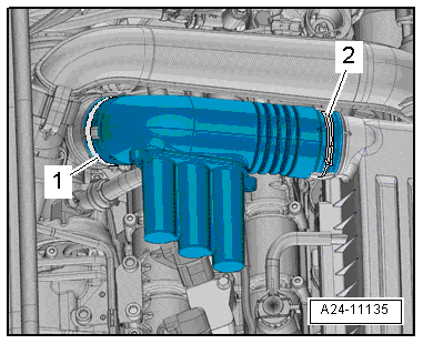
Release hose clips -1- and
-2-, and remove air pipe. |
| – |
Remove air filter housing
→ Chapter. |
| – |
Supporting engine in installation position
→ Chapter „Supporting engine in installation position“ |
|
|
|
| – |
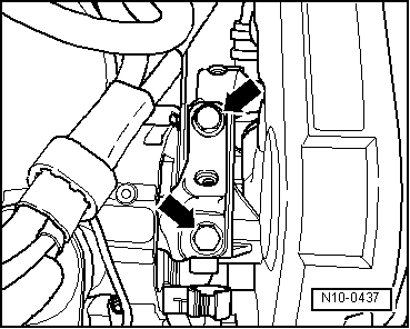
Unscrew engine mounting bolts -arrows-
one after the other and renew them (if not already renewed when
installing engine). |
| – |
First screw bolts in loosely. |
|
|
|
| – |
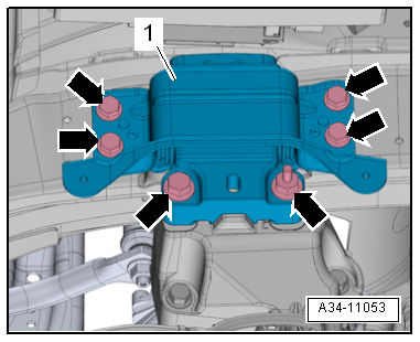
Unscrew bolts -arrows- for
gearbox mounting -1- one after the
other and renew them (if not already renewed when installing
engine). |
| – |
First screw bolts in loosely. |
|
|
|
| – |
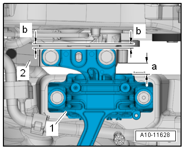
Using assembly lever, adjust engine/gearbox assembly so that
specifications listed below are attained: |
| There must be a distance of -a-
= 10 mm between engine support -2-
and engine mounting -1-. |
| Side surface of engine support casting
-2- must be located parallel to support arm of engine
mounting -1-. |
| Distance -b- = distance
-b-. |
 Note Note
| Distance -a- = 10 mm can also
be checked with a metal rod of suitable size, or similar. |
| – |
Tighten bolts for engine mounting. |
|
|
|
| – |
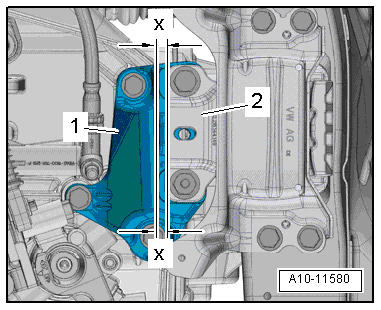
On the gearbox side, ensure that the edges of the support
arm -2- and gearbox support
-1- are parallel. |
| Distance -x- = distance
-x-. |
| – |
Tighten bolts for gearbox mounting. |
| Install in reverse order. |
| → Chapter „Assembly overview - assembly mountings“ |
| → Chapter „Assembly overview - charge air system“ |
| → Electrical system; Rep. gr.27 |
| → Chapter „Assembly overview - air filter housing“ |
| → Chapter „Assembly overview - assembly mountings“ |
|
|
|
Procedure
The following specifications must be obtained:
There must be a distance of - ...
Other materials:
Overview of the driver door
Fig. 4 Overview of the controls in the
driver door (left-hand drive vehicles) The controls are mirrored for right-hand
drive vehicles
Key for :
Door release lever
Central locking buttons for locking
and unlocking the vehicle –
Switch for adjusting the exterior ...
Removing and installing condensation drain (RHD)
Removing
–
Remove right centre console trim in footwell
→ General body repairs, interior; Rep. gr.68.
–
Carefully push floor covering aside and cover it in area
under condensati ...
Rain sensor
Fig. 89 Windscreen wiper lever: setting
the rain sensor ①
Fig. 90 Sensitive surface of the rain sensor
First read and observe the introductory information
and safety warnings When the rain sensor is activated, it automatically controls
the frequency of the wiper intervals, depending o ...
© 2016-2024 Copyright www.vwgolf.org

 Checking adjustment of assembly mountings (engine and gearbox mountings)